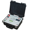
TTRM 301
SCOPE introduces state of the art precision three phase Transformer Turns Ratio Meter (TTRM ) designed for field testing as well as factory testing of power transformers, instrument transformers and distribution transformers of all types. Along with turns ratio, this light weight and reliable instrument measures ratio deviation, phase angle deviation, magnetizing current and detects tap-position of single as well as three phase transformers in charged switchyard condition. The instrument has facility to automatically detect vector group of all majority configurations available. The differant AC voltage selection offers high accuracy in measurement.
Instrument has in-built TFT display with touch screen and thermal printer. The user friendly, simple instrument makes the testing more easy. With the touch keypad it is possible to enter required DUT information. The ratio results of all the phases are displayed in tabular form with % error. Internal non volatile memory gives the provision of storing test results. Further data can be downloaded to PC or copied to memory stick through USB port provided. The CTrans-TTRM software, gives the flexibility to download the stored results to PC and do the further analysis and report generation.
Features
- Different voltage ranges provided for more accurate results
- 5.7” TFT display with touch screen and simple menus to operate TTRM
- Facility to configure transformer ID and details
- Automatic OLTC operation for tap change
- Date and time stamping to results
- In-build memory to store the test results
- Thermal printer to take quick print out for record
- Ethernet port for PC interface to transfer records to PC Software
- Mass storage device (USB 2.0) interface for copying records in pen drive
- Lightweight,portable instrument household in rugged moulded case
Specifications
| Parameter | Display | Range | Resolution | Accuracy | |
| 1 | Turns Ratio | 1.9999 : 1 | 0.8-20000 : 1 | 5 Digit |
0.8 - 100: ± 0.05% @ 10V 101 - 1000: ± 0.05% @ 10V 1001 - 1500: ± 0.05% @ 10V 1501 - 2000: ± 0.10% @ 10V 2001 - 4000: ± 0.20% @ 10V
0.8 - 100: ± 0.05% @ 40V 101 - 1000: ± 0.05% @ 40V 1001 - 1500: ± 0.05% @ 40V 1501 - 2000: ± 0.05% @ 40V 2001 - 4000: ± 0.05% @ 40V 4001 - 13000: ± 0.25% @ 40V
0.8 - 100: ± 0.03% @ 100V 101 - 1000: ± 0.05% @ 100V 1001 - 1500: ± 0.05% @ 100V 1501 - 2000: ± 0.05% @ 100V 2001 - 4000: ± 0.05% @ 100V 2001 - 4000: ± 0.05% @ 100V 13001 - 20000: ± 0.20% @ 100V |
| 2 | Excitation Current | 0.1mA to 1.999A | 0-2A | 0.1mA | ± 1mA |
| 3 | Phase Deviation | 0.05 Deg to +179.95 Deg | ± 180 Deg | 0.05 Deg | ± 0.05 Deg |
| Parameters | TTRM 301 |
| No of channels | Three HV channels and three LV channels |
| Test Voltages | 10V, 40V and 100V AC selectable voltages |
| Measurements | Ratio, Ratio error |
| OLTC Control | Raise and Lower control to operate OLTC |
| Test Results Display | (TFT) display, Thermal Printer. |
| Test Leads | Suitable to test EHV Transformers |
| Paper | Thermal, 58 mm wide roll form |
| Memory | Inbuilt memory, can store 50000 records, with date and time stamping. USB port to copy record in pen drive |
| Power | 90V – 265V, 50/60 Hz, 100VA approx. |
| Communication Port | Ethernet port. |
| Housing | Fitted in moulded case |
| Environment | 0 to 50 C, 95% RH (non-condensing) Electrical noise normally found in charged EHV switchyards |
| Dimensions | 435 X 315X 175 mm. (Max.) |
| Weight | 10 Kg Approx |
TTRM 302
SCOPE introduces state of the art precision three phase Transformer Turns Ratio Meter (TTRM ) designed for field testing as well as factory testing of power transformers, instrument transformers and distribution transformers of all types. Along with turns ratio, this light weight and reliable instrument measures ratio deviation, phase angle deviation, magnetizing current and detects tap-position of single as well as three phase transformers in charged switchyard condition. The instrument has facility to automatically detect vector group of all majority configurations available. The differant AC voltage selection offers high accuracy in measurement.
Instrument has in-built TFT display with touch screen and thermal printer. The user friendly, simple instrument makes the testing more easy. With the touch keypad it is possible to enter required DUT information. The ratio results of all the phases are displayed in tabular form with % error. Internal non volatile memory gives the provision of storing test results. Further data can be downloaded to PC or copied to memory stick through USB port provided. The CTrans-TTRM software, gives the flexibility to download the stored results to PC and do the further analysis and report generation.
Features
- Different voltage ranges provided for more accurate results
- 5.7” TFT display with touch screen and simple menus to operate TTRM
- Facility to configure transformer ID and details
- Automatic OLTC operation for tap change
- Date and time stamping to results
- In-build memory to store the test results
- Thermal printer to take quick print out for record
- Ethernet port for PC interface to transfer records to PC Software
- Mass storage device (USB 2.0) interface for copying records in pen drive
- Lightweight,portable instrument household in rugged moulded case
Specifications
| Parameter | Display | Range | Resolution | Accuracy | |
| 1 | Turns Ratio | 1.9999 : 1 | 0.8-20000 : 1 | 5 Digit |
0.8 - 100: ± 0.05% @ 10V 101 - 1000: ± 0.05% @ 10V 1001 - 1500: ± 0.05% @ 10V 1501 - 2000: ± 0.10% @ 10V 2001 - 4000: ± 0.20% @ 10V
0.8 - 100: ± 0.05% @ 40V 101 - 1000: ± 0.05% @ 40V 1001 - 1500: ± 0.05% @ 40V 1501 - 2000: ± 0.05% @ 40V 2001 - 4000: ± 0.05% @ 40V 4001 - 13000: ± 0.25% @ 40V
0.8 - 100: ± 0.03% @ 100V 101 - 1000: ± 0.05% @ 100V 1001 - 1500: ± 0.05% @ 100V 1501 - 2000: ± 0.05% @ 100V 2001 - 4000: ± 0.05% @ 100V 2001 - 4000: ± 0.05% @ 100V 4001-13000: ± 0.15% @ 100V 13001 - 20000: ± 0.20% @ 100V |
| 2 | Excitation Current | 0.1mA to 1.999A | 0-2A | 0.1mA | ± 1mA |
| 3 | Phase Deviation | 0.05 Deg to +179.95 Deg | ± 180 Deg | 0.05 Deg | ± 0.05 Deg |
| Parameters | TTRM 302 |
| No of channels | Three HV channels and three LV channels |
| Test Voltages | 10V, 40V and 100V AC selectable voltages |
| Measurements |
Ratio, Ratio error, Phase Angle Deviation, Excitation current, Vector group and Magnetic balance (optional) |
| OLTC Control | Raise and Lower control to operate OLTC |
| Test Results Display | 5.7” touch-screen (TFT) display, thermal printer |
| Test Leads | Suitable to test EHV Transformers |
| Paper | Thermal, 58 mm wide roll form |
| Memory | Up to 50000 records inbuilt memory, with date and time stamping |
| Power | (110V ± 15%) / (60Hz ± 10%) OR (230V ± 15%) / (50Hz ± 10%), 75VA. |
| Communication Port | Ethernet port for PC Communication, USB port for data downloading to pen-drive |
| Housing | IP 65 rated moulded case |
| Operating Environment | -20°C to +55°C, 95%RH (non-condensing) |
| Storage Environment | -40°C to +60°C, 95%RH (non-condensing) |
| Dimensions | 435 X 315X 175 mm. (Max.) |
| Weight | 10 Kg Approx |
TTRM 102
SCOPE introduces state of the art precision single phase Transformer Turns Ratio Meter (TTRM ) designed for field testing as well as factory testing of power transformers, instrument transformers and distribution transformers of all types. TTRM 102 along with turns ratio, measures ratio deviation, phase angle deviation, magnetizing current and detects tap-position of single phase transformer in charged switchyard condition. The range of AC voltage selection offers high accuracy in measurement.Both the instrument have in-built TFT display with touch screen and thermal printer. The user friendly, simple instrument makes the testing more easy. With the touch keypad it is possible to enter required DUT information.The ratio results are displayed with % error. Internal non-volatile memory gives the provision of storing test results.Further data can be downloaded to PC or copied to memory stick through USB port provided.
The C-Trans-software, gives the flexibility to download the stored results to PC and do the further analysis and report generation.
Features
- Different voltage ranges provided for more accurate results
- 5.7” TFT display with touch screen and simple menus to operate TTRM
- Facility to configure transformer ID and details
- Automatic OLTC operation for tap change
- Date and time stamping to results
- In-build memory to store the test results
- Thermal printer to take quick print out for record
- Ethernet port for PC interface to transfer records to PC Software
- Mass storage device (USB 2.0) interface for copying records in pen drive
- Lightweight, portable instrument household in rugged moulded case
Specifications
| Parameter | Test Voltage | Range | Resolution | Accuracy | |
| 1 |
Ratio | 10 V | 0.8000 – 9.9999 | 0.0001 |
0.05 % |
| 10.000 – 99.999 | 0.001 |
0.05 % |
|||
| 100.00 – 999.99 | 0.01 | 0.05 % | |||
| 1000.0 – 1500.0 | 0.1 | 0.05 % | |||
| 1500.1 – 2000.0 | 0.1 | 0.1 % | |||
| 2000.1 – 4000.0 | 0.1 | 0.2 % | |||
| 40 V | 0.8000 – 9.9999 | 0.0001 | 0.05 % | ||
| 10.000 – 99.999 | 0.001 | 0.05 % | |||
| 100.00 – 999.99 | 0.01 | 0.05 % | |||
| 1000.0 – 4000.0 | 0.1 | 0.05 % | |||
| 4000.1 – 9999.9 | 0.1 | 0.25 % | |||
| 10000 - 13000 | 1 | 0.25 % | |||
| 100 V | 0.8000 – 9.9999 | 0.0001 | 0.03 % | ||
| 10.000 – 99.999 | 0.001 | 0.03 % | |||
| 100.00 – 999.99 | 0.01 | 0.05 % | |||
| 1000.0 – 4000.0 | 0.1 | 0.05 % | |||
| 4000.1 – 9999.9 | 0.1 | 0.15 % | |||
| 10000 – 13000 | 1 | 0.15 % | |||
| 13001 - 20000 | 1 | 0.20 % | |||
| 2 |
Excitation Current |
10 V | 2000 mA | 0.1 mA | ± 1 mA |
| 40 V | 500 mA | 0.1 mA | ± 1 mA | ||
| 100 V | 200 mA | 0.1 mA | ± 1 mA | ||
| 3 | Phase Deviation |
10V / 40V / 100 V |
± 180 Degree | 0.01 Degree | ± 0.05 Degree |
| Parameters | TTRM 102 |
| No of channels | single HV channel and single LV channel |
| Test Voltages | 10V, 40V and 100V AC selectable voltages |
| Measurements | Ratio, Ratio error, Phase Angle Deviation, Excitation Current |
| OLTC Control | Raise and Lower control to operate OLTC |
| Test Results Display | (TFT) display, Thermal Printer. |
| Test Leads | Suitable to test EHV Transformers |
| Printer | Inbuilt Thermal Printer |
| Paper | Thermal, 58 mm wide roll form |
| Memory | Inbuilt memory, can store 50000 records, with date and time stamping. USB port to copy record in pen drive |
| Power | (110V ± 15%) / (60Hz ± 10%) OR (230V ± 15%) / (50Hz ± 10%), 75VA.. |
| Communication Port | Ethernet port. |
| Housing | Fitted in moulded case |
| Environment | 0: -20°C to 55°C 95%RH (non-condensing) Electrical noise normally found in charged EHV switchyards |
| Dimensions | 435 X 315X 175 mm. (Max.) |
| Weight | 10 Kg Approx |
TRM 104
TRM104 is a portable winding resistance meter, designed to work in live EHV switchyards. Winding resistance values of large transformers up to 500 MVA and rotating machines are directly displayed. The meter is protected against the back emf offered by large inductive winding. A back-lit 4 line LCD with a user-friendly menu sets up the instrument for the test. Winding resistances and safety messages are also shown on this display. It is possible to measure the resistance of two windings simultaneously.The meter contains a special power source for rapid stabilization of test results.
A 30V DC, 10 Amp power source, controlled strategically by digital means passes the selected current through the winding. Precision instrumentation amplifiers read voltage developed across the windings and the ohmic values are directly displayed. Use of the classical Kelvin’s 4-wire method ensures reliable measurement. Specially designed thermal management of power source enables measurement over longer periods, when delta connected generator transformers are tested. The TRM is capable of identifying the interruption of injected current during tap change of OLTC. A beeper alarm during current injection ensures operator safety during measurement.
Features
- Winding resistance values of large transformers upto 500 MVA and rotating machines are directly displayed.
- Portable winding resistance meter, designed to work in live EHV switchyards.
- Protected against the back emf off ered by large inductive windings.
- A backlit 4 line LCD with a user-friendly menu sets up the instrument for the test. Winding resistances and safety messages are also shown on this display.
- Possible to measure the resistance of two windings simultaneously.
- The meter contains a special power source for rapid stabilisation of test results
Specifications
| Parameter | TRM 104 |
| No of Channels | Two, for simultaneous measurement on 2 windings |
| Current Ranges | 10A, 1A, 100mA, 10mA |
| Resistance Ranges | Up to 2000 Ω (Auto ranging) |
| Resolution | 4 ½ digit |
| Accuracy | Value ± 0.5% ± 2 digits |
| Open Circuit Voltage | 30 V |
| Display | One backlit 4 line LCD display for interactive menu |
| Test Leads | 20m, suitable to test HV/EHV transformers |
| Environment | 0°C to 50°C, 95% RH (non condensing) |
| Input Supply | 230 VAC ± 15%, 50 Hz ± 10%, 400 VA approx |
| Dimensions | 475 x 405 x 230 mm |
| Weight | 15 Kg. Approx |
TRM 104+
TRM104+ is a portable winding resistance meter, housed in rugged moulded case, designed to work in live EHV switchyards. Winding resistance values of large transformers up to 500 MVA and rotating machines are directly displayed. The meter is protected against the back emf offered by large inductive winding. A back-lit 4 line LCD with a user-friendly menu sets up the instrument for the test. Winding resistances and safety messages are also shown on this display. It is possible to measure the resistance of two windings simultaneously. The meter contains a special power source for rapid stabilization of test results.
A 30V DC, 10 Amp power source, controlled strategically by digital means passes the selected current through the winding. Precision instrumentation amplifiers read voltage developed across the windings and the ohmic values are directly displayed. Use of the classical Kelvin’s 4-wire method ensures reliable measurement. Specially designed thermal management of power source enables measurement over longer periods, when delta connected generator transformers are tested. The TRM is capable of identifying the interruption of injected current during tap change of OLTC. A beeper alarm during current injection ensures operator safety during measurement.
Features
- Winding resistance values of large transformers up to 500 MVA and rotating machines are directly displayed.
- Portable winding resistance meter, designed to work in live EHV switchyards.
- Protected against the back emf offered by large inductive windings.
- A backlit 4 line LCD with a user-friendly menu sets up the instrument for the test. Winding resistances and safety messages are also shown on this display.
- Possible to measure the resistance of two windings simultaneously.
- The meter contains a special power source for rapid stabilisation of test results
Specifications
| Parameter | TRM 104+ |
| No of Channels | Two, for simultaneous measurement on 2 windings |
| Current Ranges | 10A, 5A, 1A, 100mA, 10mA |
| Resistance Ranges | Up to 2000 Ω (Auto ranging) |
| Resolution | 4 ½ digit |
| Accuracy | Value ± 0.5% ± 2 digits |
| Open Circuit Voltage | 30 V |
| Display |
One backlit 4 line LCD display for interactive menu, keyboard functions, messages and test results 4 and 1⁄2 digit display for resistance, 3 and 1⁄2 digit display for test current |
| Test Leads | 20m, suitable to test HV/EHV transformers |
| Environment | 0°C to 50°C, 95% RH (non condensing) |
| Input Supply | 90 - 260V AC, 47-63 Hz, 25VA (approx.) |
| Dimensions | 406 x 305 x 229 mm |
| Weight | 12 Kg. Approx. |
DIR CT
SCOPE proudly introduces Dir CT, a CT Polarity Tester specially designed to verify correctness of polarity of current transformers cores in live EHV switchyards. Polarity test is one of the most common yet crucial tests required to be done on current transformers by commissioning as well as maintenance engineers. Even though it is commonly conducted check, there was no all in one simple tool available for this measurement. DIR CT fills this void to perfection, it is expected to significantly reduce the time taken for polarity checks on numerous CT in sub-station, especially during commissioning of new sub-stations
It is must have tool for Testing & Commissioning companies.
Features
- Simple, Portable, Lightweight, Handheld device.
- Easy and fast one push-button operation.
- Gives analog indication (Forward & Reverse) of current transformer polarity.
- Tests various types of CTs.
- Works on easily available AA size alkaline batteries.
- Gives reliable performance even after continuous usage
CRM 100B
CRM 100B directly measures micro-ohm values at 100 Amps DC under live switchyard conditions.
CRM 100B is specially designed to reliably measure contact resistance of circuit breakers, isolators, busbar joints, welded joints etc., under the hostile electrostatic noise found in live EHV switchyards upto 765 kV.
Inbuilt rechargeable battery tremendously enhances utility as AC supply connectivity is not required.
CRM 100B operates on a rechargeable battery as well as Mains supply. It has a built-in constant current source, a precision instrumentation amplifi er, digital readout and control logic.A pulse of 100A DC is passed through the test object and voltage drop is sensed using the classical Kelvin’s 4 wire method to measure contact resistance. Both test current and resistance value are displayed on LCD.
Features
- A radically new design makes CRM the lightest available contact resistance meter.
- Battery as well as Mains operated.
- Direct display of micro-ohm value does away with manual calculations.
- Fool-proof connections and repeatability are ensured by
- SCOPE’s specially designed proprietory Ck clamps.
- Supplied with rugged calibrated test lead set suitable for 4 wire measurement.
Specifications
- Ranges : 199.9μΩ and 1999μΩ
- Resolution : 0.1μΩ and 1μΩ
- Accuracy : Value ± 2 % ± 1 digit
- Current : 100 A DC
- Displays : Two, 3½ digit, ½ inch LCD, for current and resistance values
- Power : 230 V AC ± 15%, 50 Hz ± 10%, 75 VA
- Battery : Instrument operates on inbuilt rechargeable battery (2 nos. 6V, 4.5Ah)
- Dimensions : 435 x 350 x 170 mm
- Weight : 9 kg, instrument
- Environment: 0° to 50° C max, 95 % RH (non-condensing), Live EHV switchyard environment
CRM 100C
CRM 100C directly measures resistance values with DC current injection under live switchyard conditions.The CRM 100C is specially designed to reliably measure contact resistance of Circuit Breakers, Isolators, Bus Bar joints, welded joints etc., under the hostile electrostatic noise found in live EHV switchyards. It can also be used for testing cables, graphite bars etc.
It has a truly continuous current source without any ON/OFF duty cycle
Features
- Innovative design makes CRM 100C the lightest available continuous current contact resistance meter
- Direct display of micro-ohm value does away with manual calculations
- Fool-proof connections and repeatability are ensured by SCOPE’s specially designed proprietory Ck clamps
- Supplied with rugged calibrated test lead set satisfying Kelvin’s 4 wire measurement principle.
- Selectable current ranges allows user to test various DUTs having wide resistance range.
- Every current range is associated with selectable resistance range to achieve better resolution of results.
- LED indication makes user aware about current injection status.
- User-friendly Menu structure enables user to take test easily.
- PC downloading facility is available with CData – PC Downloading & Data Management Software.(Optional)
Specifications
- Current : 10, 20, 50, 100A DC
- Accuracy : Value ± 0.5 % ± 5 digit
- Display : One backlit 4 line LCD for interactive menu, test results, keyboard functions and messages,test results, 3½ digit for resistance and current values
- Power : 230 V AC ± 15%, 50 Hz ± 10%, 500 VA
- Dimensions : 475 x 405 x 175 mm
- Weight : 11 kg, instrument
- Environment: 0° to 50° C max, 95 % RH (non-condensing), Live EHV switchyard environment
- Ranges : On SCOPE’s Calibrated Test Leads as follows
| Test Current | Resistance Range | Resolution |
| 100A |
199.9µΩ 1999µΩ 19.99mΩ |
0.1µΩ 1µΩ 0.01mΩ |
| 50A | 1999µΩ
19.99mΩ |
1µΩ
0.01mΩ |
| 20A | 1999µΩ
19.99mΩ 199.9mΩ |
1µΩ
0.01mΩ 0.1mΩ |
| 10A | 19.99mΩ
199.9mΩ 1999mΩ |
0.01mΩ
0.1mΩ 1mΩ |
CRM 100C+
CRM 100C+, housed in moulded case fitted with inbuilt thermal printer, directly measures resistance values with DC current injection under live switchyard conditions. The CRM 100C+ is specially designed to reliably measure contact resistance of Circuit Breakers, Isolators, Bus Bar joints, welded joints etc., under the hostile electrostatic noise found in live EHV switchyards. It can also be used for testing cables, graphite bars etc.
It has a truly continuous current source without any ON/OFF duty cycle
Features
- Innovative design makes CRM 100C+ the lightest available continuous current contact resistance meter
- Direct display of micro-ohm value does away with manual calculations
- Fool-proof connections and repeatability are ensured by SCOPE’s specially designed proprietary Ck clamps
- Supplied with rugged calibrated test lead set satisfying Kelvin’s 4 wire measurement principle.
- Selectable current ranges allows user to test various DUTs having wide resistance range.
- Every current range is associated with selectable resistance range to achieve better resolution of results.
- LED indication makes user aware about current injection status.
- User-friendly Menu structure enables user to take test easily.
- PC downloading facility is available with C-Data – PC Downloading & Data Management Software.(Optional)
Specifications
- Current : 10, 20, 50, 100A DC
- Accuracy : Value ± 0.5 % ± 5 digit
- Display : One backlit 4 line LCD for interactive menu, test results, keyboard functions and messages, test results, 3½ digit for resistance and current values
- Printer : Inbuilt thermal Printer
- Power : 230 V AC ± 15%, 50 Hz ± 10%, 1500 VA
- Dimensions : 429 x 328 x 236 mm approximately
- Weight : 9 kg, instrument
- Environment: 0° to 50° C max, 95 % RH (non-condensing), Live EHV switchyard environment
- Ranges : On SCOPE’s Calibrated Test Leads as follows
| Test Current | Resistance Range | Resolution |
| 100A |
199.9µΩ 1999µΩ 19.99mΩ |
0.1µΩ 1µΩ 0.01mΩ |
| 50A | 1999µΩ
19.99mΩ |
1µΩ
0.01mΩ |
| 20A | 1999µΩ
19.99mΩ 199.9mΩ |
1µΩ
0.01mΩ 0.1mΩ |
| 10A | 19.99mΩ
199.9mΩ 1999mΩ |
0.01mΩ
0.1mΩ 1mΩ |