
Super User
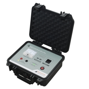
The new generation CFL AG2 Cable Fault Audio Generator from SCOPE is the ultimate solution for locating the underground cable lay in minimum time. It uses advanced technologies for auto impedance matching, and stabilised frequency which helps even an unskilled operator to locate the cable accurately.
CFL AG2 portable Audio Generator to locate the exact route of the underground cable in conjunction with Pin Pointer cum Rote Tracer i.e., CFL PP Series. This configuration is also used for depth determination of the cable and pinpointing of low resistance faults. Various modes of operation combined with advanced features offer users the most effective solution for the job.
Features
- Compact, Lightweight and Rugged
- Operation via User Friendly Interface
- Variable output power up to 20 Watt
- Automatic load matching
- Works eff ectively with high impedance loads
- Quartz Stabilised Frequency
- Continuous or Pulsed signal injection
- Over current protection
- Water resistant and dust proof design
Specifications
| Parameters | CFL AG2 |
| Output Power | 20W Maxiumum |
| Maxiumum Output Current | 2.8A±20% |
| Frequency | 1KHz sine wave |
| Output Voltage | 4-7V/15-25V/30-40V/60-70V/90-100V/150-170V/200-230V |
| Display | Analog Meter for Output Current |
| Input Power Supply | AC 230V ±10%, 50Hz ±10% |
| Protection | Over Current / Load |
| Environmental (Operation) | 0°C to 50°C, 95% RH (Non-Condensing) |
| Environmental (Storage) | -10°C to 60°C, up to 98% RH (Non-Condensing) |
| Dimension | 275mm x 255mm x 130mm |
| Weight | 4kg |

Underground cable faults cannot be avoided due to many factors such as road widening, infrastructure improvement, digging carried out for repairs of other underground utilities etc.
The new generation CFL PL4 Cable Fault Prelocator from SCOPE is the ultimate solution for locating underground cable faults in minimum time. It uses advanced technology for fault distance measurement which helps even an unskilled operator to locate the fault accurately.
CFL PL4 portable Prelocator is used for identification of fault types in underground cables and the distance of fault. These products are designed to fi nd out various types of faults in the cable such as Open Circuit, Short Circuit, Splice in Cable, High Resistance, Moisture Ingress, etc. Various modes of operation combined with advanced features off ers user the most effective solution for the job.
Features
- User friendly operation
- Wide measurement range up to 64km
- Highest measurement accuracy of ±1% of selected range
- High speed sampling of 200MHz
- Automatic Cable End detection
- Automatic Fault Point detection
- Zoom function for detailed analysis of the waveform
- Asynchronous interference & noise suppression
- Adjustable Gain and Balance
- Inbuilt memory to store 300 waveforms with USB connectivity
- "Print-screen" function to save image in JPG
- PC Software for waveform analysis and report preparation
- High resolution 8” Colour Touchscreen display
- Mains as well as Inbuilt Rechargeable Battery operated
- Housed in weather proof molded case
Specifications
| Parameters | CFL PL4 |
| Modes of Operation |
TDR SIM / MIM / ARC (Up to 8 Fault Traces) ICM/ICE Voltage Decay |
| Sampling Rate | 200 MHz |
| Measurement Range | Up to 64 km |
| Measurement Accuracy | ±1% |
| Best Resolution | 1m |
| Pulse Amplitude (OCV) | 30V |
| Pulse Width | 40nS to 10µS |
| Output Impedance | 5Ω to 87Ω |
| Velocity of Propagation (V) | 90 - 300 m/µs |
| Memory | 300 Waveforms |
| Connectivity | USB, Direct Download to Pen drive |
| Display | 8” Colour Touchscreen LCD |
| Battery | Rechargeable Lithium Ion, Suitable for 8 hour operation |
| Power Supply | 90V to 264V AC, 47 to 63 Hz, Single Phase |
| Environmental (Operation) | -10°C to +50°C, up to 95% RH (Non-Condensing) |
| Environmental (Storage) | -20°C to 70°C, up to 98% RH (Non-Condensing) |
| Dimension | 339mm x 295mm x 152mm |
| Weight | 4.5 kg |
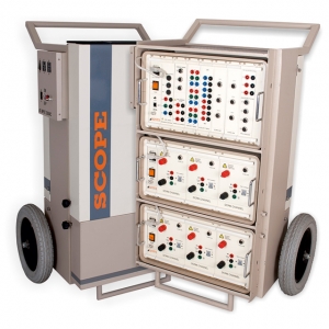
HISAC Ultima – new generation Circuit Breaker Dynamic Test Set from SCOPE …. The ultimate solution for testing Circuit Breakers of all types. HISAC Ultima is the most complete analyser for checking the dynamic performance of CBs in live EHV switchyards upto 765 kV.
HISAC Ultima can carry out Dynamic Contact Resistance Measurement on SIX breaks of THREE poles in one operation thereby significantly reducing stress on CB & testing downtime.
It offers flexibility to create pre-programmed Test Plans including all test settings for all types of circuit breakers available in a switchyard that can simply be recalled at the time of actual testing. This saves you from doing all settings in switchyards.
The Analysis software offers a range of utilities which enables effective Condition Monitoring of CB by comparing present test data with previous signatures and predicting future performance.
Features
- Tests all types of circuit breakers - LV, HV & EHV for all critical performance parameters of all the poles / breaks in a single shot.
- Measures Main/PIR contact timings, bounce, non simultaneity of contacts and auxiliary contact timings.
- Analyses contact travel characteristics for speed, insertion, contact gap, over-travel and rebound with suitable transducer and mounting fixture.
- Records trip and close coil current characteristics.
- Registers the signature of Dynamic Contact Resistance of main and arcing contacts, of all the 6 breaks simultaneously.
- Displays settings, graphical and tabulated test results.
- Prints test report in graphical format with test header and calculation footer, on external printer(not supplied).
- Incorporates powerful and practical Windows™ based Test Manager Software to control & operate instrument; view, analyze and handle graphical test data on a laptop at high resolution.
- Selects pre-programmed setup parameters and pass/fail limits through software.
- Connects to CB with wear resistant test leads of sufficient length, having quick-fit connectors, suitable for EHV circuit breakers.
- Moves easily within switchyard as the set can be mounted on a specially designed Trolley having large wheels & mains supply distribution board.
- Travel – For evaluating travel characteristics of operating mechanisms, SCOPE offers rotary and linear resistive travel transducers with universal / specially designed fixtures to suit variety of CBs available.
- DCRM module captures dynamic variation in contact resistance of main & arcing contacts during breaker operation.
- Each DCRM module has in built independent isolated, rechargeable battery based 100A DC source.
- The result is plotted in graphical form on the software screen, which can be further analysed for finding parameters such as contact gap, total insertion, arcing tip insertion, main and arcing contact resistance values etc.
- Additional optional modules are available to measure PIR value and for monitoring Station DC (Coil voltage), Motor current or other static parameters through configurable Analog channels.
- Type Tested as per IEC 60068, IEC 61326 & IEC 61010-1. CE marked
- Supplied with suitable Test Leads & aluminium transport cases for instruments.
- Travel Transducer and fixture as per order based on make, type & rating of CB.
Specifications
| Parameter | HISAC Ultima |
| Trigger Options | O, C, C-O, O-C, O-C-O |
| Timing Channel | 24 : 4 Main + 4 PIR per pole, 3 poles Simultaneously |
| Auxiliary Contact Timing Channel | 8 : 4 dry + 4 wet Expandable up to 6 Dry + 6 Wet |
| Best Time Resolution | 50μS |
| Coil Current Channel | 3 : Trip / Close coil current optionally expandable up to 6 |
| Travel Channel | 3 : Travel characteristic optionally expandable up to 6 |
| Analog Channel for DCRM Input (Optional) | 1 / 2 / 3 / 6 – as per DCRM modules selected |
| DCRM Resistance Range & Current (Optional) | 1000 / 2000 / 4000 / 8000 μΩ Selectable, Current 100A DC |
| Static Contact Resistance (CRM) Channel | As per DCRM modules selected |
| CRM Resistance Range | 1000 / 2000 / 4000 / 8000 μΩ Selectable |
| Configurable Analog Channel (Optional) | Up to 6: For inputs of station battery voltage, PIR value etc. |
| PIR value Measurement (Optional) | 0-5000Ω with the resolution of 1Ω |
| Sampling Speed | 1 / 2 / 5 / 10 / 20 kC Selectable |
| Display | Display of laptop |
| Operation | Interactive menu through laptop |
| PC Connectivity | Ethernet |
| Printer | External through laptop |
| Memory | Memory of laptop |
| Dimensions | Analyser - 500 x 270 x 300 mm, DCRM Rack - 500 x 270 x 250 mm |
| Instrument Weight | Analyser - 12 kg DCRM Rack-18 Kg(3 DCRM modules per Rack) |
| Power | 230 V AC ± 15% , 50Hz ± 10% |
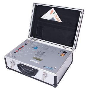
SCOT series of CB Time Interval Meters from SCOPE are compact and reliable instruments to measure operating time of all types of HV/EHV circuit breakers under charged swichyard conditions up to 400kV.
SCOT M3K measures and displays CLOSE, OPEN and CLOSE-OPEN time of main contacts of 3 poles connected end to end, simultaneously.
Features
- Inbuilt clock to tag date and time of test to the readings
- 4 line 20 character backlit LCD display for menu and results
- Inbuilt memory to hold results of last fi fty tests
- Easy to use menu driven user interface for operating
- Diagnostics for instrument condition and calibration watch
- Select the operation and mode to be performed e.g. Close, Open or CLOSE-OPEN
- Operation times of all three poles are measured and displayed simultaneously on the display
- Test results can be stored and downloaded to a PC using SCOPE’s CDATA software
Specifications
| Parameters | SCOT M3K |
| Channels | 3 |
| Breaker Control | Solid state contacts rated 300V / 30A for breaker operation |
| Output | 4 line 20 character backlit LCD RS 232C port for downloading data to PC |
| Range | 999ms maximum |
| Resolution | 1ms |
| Measuring Accuracy | Value ± 0.05% ± 1 digit |
| Test Leads | Set of 15m, wear resistant Test Cables |
| Environment | 0° to 50° C, 95% RH (Non-condensing) |
| Power | 230V AC ± 15%, 50Hz ± 10%, 25 VA |
| Dimensions | 430 x 345 x 160 mm |
| Instrument Weight | 6 kg |
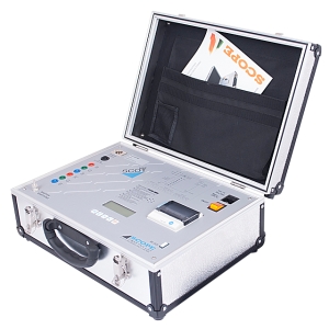
SCOT Series of CB Time Interval Meter from SCOPE are compact and reliable instruments to measure operating time of all types of HV/EHV circuit breakers under charged switchyard conditions up to 400kV.
SCOT MXP measures, displays and prints CLOSE, OPEN and CLOSE-OPEN time in various configurations. The MXP has a special mode to measure Pre-Insertion Resistor (PIR) closing time
Features
- Select the operation and mode to be performed e.g. CLOSE, OPEN or CLOSE-OPEN
- Operating time of all three poles are measured and displayed simultaneously on the display
- Test results can be stored and downloaded to a PC using SCOPE’s CDATA software
- Inbuilt clock to tag date and time of test to the readings
- 4 line 20 character backlit LCD display for menu and results
- Inbuilt memory to hold results of last 50 tests
- Easy to use menu driven user interface for operation
- Diagnostics for instrument condition and calibration watch
- Inbuilt thermal printer for printing results
Specifications
| Parameters | SCOT MXP |
| Channels | Maximum eight in PIR mode |
| Breaker Control | Solid state contacts rated 300V / 30A for breaker operation |
| Output | 4 line 20 character backlit LCD RS 232C port for downloading data to PC |
| Printer | Inbuilt thermal printer, 55mm wide roll |
| Range | 999ms maximum |
| Resolution | 1ms |
| Measuring Accuracy | Value ± 0.05% ± 1 digit |
| Test Leads | Set of 15m, wear resistant test cable |
| Environment | 0° to 50° C, 95% RH (Non-condensing) |
| Power | 230V AC ± 15%, 50Hz ± 10%, 25 VA |
| Dimensions | 430 x 345 x 160 mm |
| Instrument Weight | 6kg |
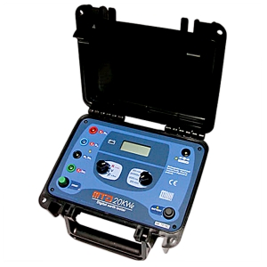
The MTD20KWR digital earth tester allows for the measurement of Earth Resistances and Soil Specific Resistivity, and also the spurious voltages caused by parasitic voltages present in the soil.
This equipment is suitable for fast and easy measurement of the grounding resistance in house and industrial buildings, hospital installations, lightning rods, antennas, substations, etc. Soil resistivity measurement allows for soil stratification in order to optimize the most complex grounding systems engineering.
Its state-of-the-art system of active and passive filters provides it with high immunity to electric interferences, making it possible to obtain reliable measurements even in the presence of spurious voltages, such as the ones that can be found in some urban areas and near primary substations.
A 1,470 Hz internal generator injects alternated current on the soil through an auxiliary rod. The voltage generated over the earth resistance is measured by the apparatus, and the resistance value is evaluated. The test current is automatically regulated.It has abnormalities indications on the display which advises the operator when the generated current is not enough to carry out reliable measurements.Because of its wide range of measurement (from 0.01 Ω up to 20 kΩ), this equipment allows for reliable testing in all kinds of soils, including those that offer very high resistivity.
This earth tester is supplied with a rechargeable internal battery. The smart charger is microprocessor-controlled, and can be powered from a 12 V car battery (or a similar one).
It has a sturdy, easy and safe to carry cabinet, with IP65 protection level (closed lid). It is suitable to work under adverse geographical and environmental conditions, with extreme temperatures in cold or tropical regions and in high mountain areas, showing a reliable performance in the field.
Features
- Digital and automatic
- Earth resistance measurement
- Ground resistivity (Wenner’s method)
- Spurious voltage measurement
- High spurious voltage rejection
- Indication of anomalies in the current circuit
- 0.01 Ω resolution
- Up to 2 kΩ resistance range
- Rechargeable NiMH battery
- IP65 rated (with closed lid)
- Graphic display (128 x 64 px)
Specifications
| Specifications | MTD20kWr | ||
| Measurement ranges |
Resistance: 0-20 kΩ Tension: 0-200 V~. |
||
| Accuracy |
Resistance measurements: ± (2% of the measured value ± 2 digits Voltage measurements: ± (2% of the measured value ± 2 digits) |
||
| Reading resolution |
0.01 Ω in the resistance measurement. 0.1 V in the voltage measurement. |
||
| Output power and current | The output power is less than 0.5 W, and the output current is limited to less than 10 mA (Peak to peak). | ||
| Battery charger | AC adapter 12 V - 1 A | ||
The MI-15KVe High-Voltage insulation tester is a truly portable device that allows the measurement of insulation resistances using test voltages up to 15kV.
It employs a state-of-the-art technology for the safe measurements of insulation resistances up to 3,000,000 MW with four test voltages: 1 kV - 5 kV - 10 kV and 15 kV.
Readings are performed through an easy-toread analogue indicator, having a broad scale.
Due to its reduced size and weight, its power autonomy and mechanical strength, this insulation tester is suitable for working out in the field, under severe weather conditions. It is powered with a rechargeable battery, with a charger for 110 V/220 V. In order to protect the equipment, the cabinet is water and dust resistant. Protection grade is IP54, and the insulation tester is supplied with a complete kit of high voltage test leads.
Features
- Insulation test up to: 3 TΩ
- 4 Test voltages: 1 kV - 5 kV - 10 kV - 15 kV
- Guard terminal
- Rechargeable battery
- Multiple scales for precision improvement
- IP-54 Protection
Specifications
| Specifications | |
| Test voltages | 1 kV - 5 kV - 10 kV - 15 kV. |
| Maximum resistance reading |
200 GΩ @ 1 kV. 1 TΩ @ 5 kV. 2 TΩ @ 10 kV. 3 TΩ @ 15 kV |
| Short circuit current | 1 mA. |
| Test voltage accuracy | ± 2% of nominal test voltages on R ≥ 10 GΩ. |
| Internal current limiting resistance |
1 MΩ @ 1 kV. 5 MΩ @ 5 kV. 10 MΩ @ 10 kV. 15 MΩ @ 15 kV. |
| Insulation tester Accuracy | Class 2 (±2 % of full scale deflection). |
| Analogue indicator | Up to 98 mm scale length, taut band, with mirror. |
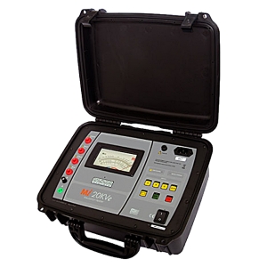
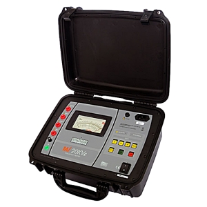
The MI-20KVe High-Voltage insulation tester is a truly portable device that allows the measurement of insulation resistances using test voltages up to 20 kV.
It employs a state-of-the-art technology for the safe measurements of insulation resistances up to 4,000,000 MΩ with four test voltages: 5 kV - 10 kV - 15 kV and 20 kV.
Analogue indicator, having a broad scale.
Due to its reduced size and weight, its power autonomy and mechanical strength, this insulation tester is suitable for working out in the field, under severe weather conditions. It is powered with a rechargeable battery, with a charger for 110 V/220 V. In order to protect the equipment, the cabinet is water and dust resistant. Protection grade is IP54, and the insulation tester is supplied with a complete kit of high voltage test leads.
Features
- Insulation test up to: 4 TΩ
- 4 Test voltages: 5 kV - 10 kV - 15 kV - 20 kV
- Guard terminal
- Rechargeable battery
- Multiple scales for precision improvement
- Portable, accurate & rugged
- IP-54 Protection
Specifications
| Specifications | |||
| Test voltages | 5 kV - 10 kV - 15 kV - 20 kV. | ||
| Maximum resistance reading |
1 TΩ @ 5 kV. 2 TΩ @ 10 kV. 3 TΩ @ 15 kV. 4 TΩ @ 20 kV. |
||
| Short circuit current | 500 µA. | ||
| Test voltage accuracy | ± 2% of nominal test voltages on R ≥ 10 GΩ. | ||
| Internal current limiting resistance |
10 MΩ @ 5 kV. 20 MΩ @ 10 kV. 30 MΩ @ 15 kV. 40 MΩ @ 20 kV. |
||
| Insulation tester Accuracy | Class 2 (±2 % of full scale deflection). | ||
| Analogue indicator | Up to 98 mm scale length, taut band, with mirror | ||
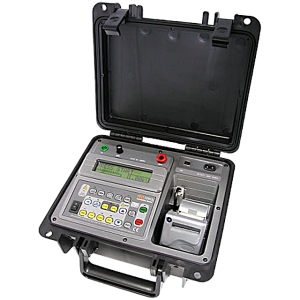
The Megabras MD-5060x is a smart, microprocessor-controlled, 5kV insulation tester and analyzer. Besides the conventional measurement of insulation resistances up to 5 TW, its advanced features allow to automatically measure both the Polarization Index and Dielectric Absorption Index, thus significantly simplifying testing of transformers.
This insulation tester is a portable, battery-powered equipment. Test voltage may be chosen from 500V to 5 kV in 100 dddV increments. Due to its measurement principle (actual voltage and current readings) the accuracy of resistance measurement is not affected by any test voltage error. Nevertheless, the High-Voltage generator is electronically stabilized with a better than 2% accuracy in open-circuit condition and for any normal operation battery voltage.
The MD-5060x is powered using a rechargeable battery and has an automatic charger that may be connected to 100 - 240V mains supply. The cabinet is strong and lightweight, easy to carry, impact-resistant and suitable to be used under severe weather conditions. Thus the megohmmeter supplies very reliable and accurate measurements both in laboratory and out in the field.
Features
- Insulation resistance
- Auto-range
- Guard terminal
- Automated tests:
- Absorption index
- Polarization index
- Real time clock
- 4000 Readings memory
- USB Interface
- Programable pass-fail
- Built-in printer
- Rechargeable battery
Specifications
| Specifications | |
| Test Voltages |
500 V, 1,000 V, 2,500 V, 5,000 V directly, one button selectable 500 V to 5 kV in 100 V increments. DC, negative. |
| Maximum resistance reading | 5 TΩ @ 5 kV. |
| Short circuit current | 1.5 ± 0.5 mA. |
| Megohmmeter basic accuracy | ± 3% of nominal test voltages on 10 GΩ. |
| Advanced features |
Automated Polarization Index calculation. Automated Dielectric Absorption Ratio calculation Programmable Pass-Fail test. Step Voltage Test. |
| Built-in printer | Prints elapsed time, actual voltage and resistance measured each 15 seconds. |