
Super User
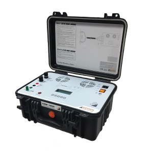
CRM 100C+, housed in moulded case fitted with inbuilt thermal printer, directly measures resistance values with DC current injection under live switchyard conditions. The CRM 100C+ is specially designed to reliably measure contact resistance of Circuit Breakers, Isolators, Bus Bar joints, welded joints etc., under the hostile electrostatic noise found in live EHV switchyards. It can also be used for testing cables, graphite bars etc.
It has a truly continuous current source without any ON/OFF duty cycle
Features
- Innovative design makes CRM 100C+ the lightest available continuous current contact resistance meter
- Direct display of micro-ohm value does away with manual calculations
- Fool-proof connections and repeatability are ensured by SCOPE’s specially designed proprietary Ck clamps
- Supplied with rugged calibrated test lead set satisfying Kelvin’s 4 wire measurement principle.
- Selectable current ranges allows user to test various DUTs having wide resistance range.
- Every current range is associated with selectable resistance range to achieve better resolution of results.
- LED indication makes user aware about current injection status.
- User-friendly Menu structure enables user to take test easily.
- PC downloading facility is available with C-Data – PC Downloading & Data Management Software.(Optional)
Specifications
- Current : 10, 20, 50, 100A DC
- Accuracy : Value ± 0.5 % ± 5 digit
- Display : One backlit 4 line LCD for interactive menu, test results, keyboard functions and messages, test results, 3½ digit for resistance and current values
- Printer : Inbuilt thermal Printer
- Power : 230 V AC ± 15%, 50 Hz ± 10%, 1500 VA
- Dimensions : 429 x 328 x 236 mm approximately
- Weight : 9 kg, instrument
- Environment: 0° to 50° C max, 95 % RH (non-condensing), Live EHV switchyard environment
- Ranges : On SCOPE’s Calibrated Test Leads as follows
| Test Current | Resistance Range | Resolution |
| 100A |
199.9µΩ 1999µΩ 19.99mΩ |
0.1µΩ 1µΩ 0.01mΩ |
| 50A | 1999µΩ
19.99mΩ |
1µΩ
0.01mΩ |
| 20A | 1999µΩ
19.99mΩ 199.9mΩ |
1µΩ
0.01mΩ 0.1mΩ |
| 10A | 19.99mΩ
199.9mΩ 1999mΩ |
0.01mΩ
0.1mΩ 1mΩ |
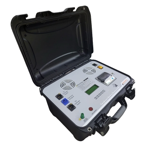
TRM104+ is a portable winding resistance meter, housed in rugged moulded case, designed to work in live EHV switchyards. Winding resistance values of large transformers up to 500 MVA and rotating machines are directly displayed. The meter is protected against the back emf offered by large inductive winding. A back-lit 4 line LCD with a user-friendly menu sets up the instrument for the test. Winding resistances and safety messages are also shown on this display. It is possible to measure the resistance of two windings simultaneously. The meter contains a special power source for rapid stabilization of test results.
A 30V DC, 10 Amp power source, controlled strategically by digital means passes the selected current through the winding. Precision instrumentation amplifiers read voltage developed across the windings and the ohmic values are directly displayed. Use of the classical Kelvin’s 4-wire method ensures reliable measurement. Specially designed thermal management of power source enables measurement over longer periods, when delta connected generator transformers are tested. The TRM is capable of identifying the interruption of injected current during tap change of OLTC. A beeper alarm during current injection ensures operator safety during measurement.
Features
- Winding resistance values of large transformers up to 500 MVA and rotating machines are directly displayed.
- Portable winding resistance meter, designed to work in live EHV switchyards.
- Protected against the back emf offered by large inductive windings.
- A backlit 4 line LCD with a user-friendly menu sets up the instrument for the test. Winding resistances and safety messages are also shown on this display.
- Possible to measure the resistance of two windings simultaneously.
- The meter contains a special power source for rapid stabilisation of test results
Specifications
| Parameter | TRM 104+ |
| No of Channels | Two, for simultaneous measurement on 2 windings |
| Current Ranges | 10A, 5A, 1A, 100mA, 10mA |
| Resistance Ranges | Up to 2000 Ω (Auto ranging) |
| Resolution | 4 ½ digit |
| Accuracy | Value ± 0.5% ± 2 digits |
| Open Circuit Voltage | 30 V |
| Display |
One backlit 4 line LCD display for interactive menu, keyboard functions, messages and test results 4 and 1⁄2 digit display for resistance, 3 and 1⁄2 digit display for test current |
| Test Leads | 20m, suitable to test HV/EHV transformers |
| Environment | 0°C to 50°C, 95% RH (non condensing) |
| Input Supply | 90 - 260V AC, 47-63 Hz, 25VA (approx.) |
| Dimensions | 406 x 305 x 229 mm |
| Weight | 12 Kg. Approx. |

SCOPE introduces 25 A state of the art precision winding resistance meter, specially designed for field testing as well as factory testing of large transformers up to 500 MVA. Winding resistance value of transformer and rotating machine are directly displayed on 5.7” TFT display. TRM 25+ is designed to work in live EHV switchyard conditions, ensuring operator’s safety and repeatability of results. Maintenance time saving is ensured by one time connection to transformer with simultaneous resistance measurement of six windings, measurement of resistances of all taps with automated tap change and demagnetization facility. The meter is protected against the back-EMF offered by large inductive windings.
Features
- Can measure DC winding resistance of large rotating machines, highly inductive test objects like Transformer, Generators and Motors etc.
- 25 A DC current makes it possible to measure low resistances with high accuracy.
- One time connection to either all windings of primary and / or secondary. Simultaneous measurement reduces connection and measurement time.
- Change in winding resistance, short or open windings can be detected from measured values.
- Automatic temperature measurement and temperature corrected value calculation.
- Measurements of winding resistance of all taps of phases in one go. Recoding, printing and storage of results.
- OLTC contact opening and compete OLTC performance test facility. Testing of either single or three phases in one test. Single report generation.
- To know condition of OLTC contacts, OLTC mechanism, transition resistor.
- Discharges and demagnetizes the object after test.
Specifications
| Parameter | TRM 25+ |
| No of Channels | 6 Current Channels, 6 Voltage Channels , 1 temperature Channel |
| Connections | One time connection to primary or secondary winding of transformer |
| Current Ranges | 25A, 10A, 5A, 1A, 100mA, 10mA |
| Resistance Ranges | Up to 2000 Ω (Auto ranging) |
| Resolution | 4 ½ digit |
| Accuracy | Value ± 0.5% ± 5 counts |
| Current and Resistance ranges | Please look for the table below |
| Open Circuit Voltage | 50 V |
| Demagnetization Facility | Yes |
| Display | 5.7” TFT display with touch screen |
| Printer | 58 mm, Inbuilt thermal printer |
| Communication Port | Ethernet for PC communication |
| Data Port | USB for extrernal memory stick connection |
| External Control | Possible via Notebook PC through Ethernet port and software |
| Temperature measurement | Range 0 to 100 deg, Accuracy ± 1 deg, Resolution 0.1deg |
| Temperature correction | For Aluminium & Copper |
| Temperature Input Channel | Compatible to accept RTD input |
| User Interface | Resistive touch screen |
| Back EMF Protection | Yes. Automatic protection after measurement and during accidental disconnection of current path. Protection operates even if Mains supply fails. |
| Discharge Facility & Indication | Automatic Discharge of DUT & messages on screen |
| Tap Changer Test | Detects discontinuity during tap changer test |
| OLTC Test Facility(Optional) | OLTC test facility with current v/s time graph, Single or Three Phases simultaneously. Available in control through PC option only. |
| OLTC current Ranges | 25A, 10A, 5A |
| Protection | Shut down of power source on Over voltage, Over current,Over temperature |
| Indications | Polarity reversal, Test connection continuity and discharge |
| Diagnostics Check | At power On instrument does self-check of channels and shows the message |
| Test Leads | Measuring leads, AC supply, earth leads and temperature sensor lead |
| Operating Environment | -10°C to 50°C, 95% RH (non condensing) |
| Storage Temperature | -20°C to 60 °C |
| Heat Run test | Yes |
| Delta connection Measurement | values of each arm of delta winding is calculated and displayed |
| One side earthing | Instrument is able to do the measurement with one side earthing (with Neutral earthing) |
| Input Supply | 110V AC ±15% 50/60 Hz ±10% Or 220V AC ±15% 50/60 Hz ±10%. |
| Dimensions | 630 x 500 x 302mm |
| Weight | 22 Kg. Approx |
| Range, Resistance & Resolutions | Current Range | ||||||
| 25A | 10A | 5A | 1A | 100mA | 10mA | ||
| Range # 1 | Resistance | 800μΩ | 2mΩ | 4mΩ | 20mΩ | 200mΩ | 2Ω |
| Resolution | 0.1μΩ | 0.1μΩ | 1μΩ | 1μΩ | 10μΩ | 100μΩ | |
| Range #2 | Resistance | 8mΩ | 20mΩ | 40mΩ | 200mΩ | 2Ω | 20Ω |
| Resolution | 1μΩ | 1μΩ | 10μΩ | 10μΩ | 100μΩ | 1mΩ | |
| Range # 3 | Resistance | 80mΩ | 200mΩ | 400mΩ | 2Ω | 20Ω | 200Ω |
| Resolution | 10μΩ | 10μΩ | 100μΩ | 100μΩ | 1mΩ | 10mΩ | |
| Range # 4 | Resistance | 800mΩ | 2Ω | 4Ω | 20Ω | 200Ω | 2000Ω |
| Resolution | 100μΩ | 100μΩ | 1mΩ | 1mΩ | 10mΩ | 100mΩ | |

HISAC Ultima – new generation Circuit Breaker Dynamic Test Set from SCOPE …. The ultimate solution for testing Circuit Breakers of all types. HISAC Ultima is the most complete analyser for checking the dynamic performance of CBs in live EHV switchyards upto 765 kV.
HISAC Ultima can carry out Dynamic Contact Resistance Measurement on SIX breaks of THREE poles in one operation thereby significantly reducing stress on CB & testing downtime.
HISAC Ultima with DCRM+ ensures end users safety by providing Dual Earth Test, in which Circuit Breaker will be grounded from both sides while conducting the test.
It offers flexibility to create pre-programmed Test Plans including all test settings for all types of circuit breakers available in a switchyard that can simply be recalled at the time of actual testing. This saves you from doing all settings in switchyards.
The Analysis software offers a range of utilities which enables effective Condition Monitoring of CB by comparing present test data with previous signatures and predicting future performance.
Features
- Tests all types of circuit breakers - HV, EHV & UHV for all critical performance parameters of all the poles / breaks in a single shot.
- Measures Main/PIR contact timings, bounce, non simultaneity of contacts and auxiliary contact timings.
- Analyses contact travel characteristics for speed, insertion, contact gap, over-travel and rebound with suitable transducer and mounting fixture.
- Records trip and close coil current characteristics.
- Registers the signature of Dynamic Contact Resistance of main and arcing contacts, of all the 6 breaks simultaneously.
- Displays settings, graphical and tabulated test results.
- Prints test report in graphical format with test header and calculation footer, on external printer(not supplied).
- Incorporates powerful and practical Windows™ based Test Manager Software to control & operate instrument; view, analyze and handle graphical test data on a laptop at high resolution.
- Selects pre-programmed setup parameters and pass/fail limits through software.
- Connects to CB with wear resistant test leads of sufficient length, having quick-fit connectors, suitable for EHV circuit breakers.
- Moves easily within switchyard as the set can be mounted on a specially designed Trolley having large wheels & mains supply distribution board.
- Travel – For evaluating travel characteristics of operating mechanisms, SCOPE offers rotary and linear resistive travel transducers with universal / specially designed fixtures to suit variety of CBs available.
- DCRM module captures dynamic variation in contact resistance of main & arcing contacts during breaker operation.
- Each DCRM module has in built independent isolated, rechargeable battery based 100A DC source.
- The result is plotted in graphical form on the software screen, which can be further analysed for finding parameters such as contact gap, total insertion, arcing tip insertion, main and arcing contact resistance values etc.
- Additional optional modules are available to measure PIR value and for monitoring Station DC (Coil voltage), Motor current, First Trip Analysis or other static parameters through configurable Analog channels.
- Type Tested as per IEC 60068, IEC 61326-1 & IEC 61010-1
- Supplied with suitable Test Leads & transport cases for instruments.
- Travel Transducer and fixture as per order based on make, type & rating of CB.
Specifications
| Parameter | HISAC Ultima with DCRM+ |
| Trigger Options | O, C, C-O, O-C, O-C-O |
| Timing Channel | 24 : 4 Main + 4 PIR per pole, 3 poles Simultaneously |
| Auxiliary Contact Timing Channel | 8 : 4 dry + 4 wet Expandable up to 6 Dry + 6 Wet |
| Coil Current Channel | 3 : Trip / Close coil current optionally expandable up to 6 |
| Travel Channel | 3 : Travel characteristic optionally expandable up to 6 |
| Analog Channel for DCRM Input (Optional) | 2 / 4 / 6 – as per DCRM modules selected |
| DCRM Resistance Range & Current (Optional) | 1000 / 2000 / 4000 / 8000 μΩ Selectable, Current 100A DC |
| Static Contact Resistance (CRM) Channel | As per DCRM modules selected |
| CRM Resistance Range | 1000 / 2000 / 4000 / 8000 μΩ Selectable |
| Configurable Analog Channel (Optional) | Up to 6: For inputs of station battery voltage, PIR value etc. |
| PIR value Measurement (Optional) | 0-5000Ω with the resolution of 1Ω |
| Sampling Speed | 1 / 2 / 5 / 10 / 20 kC Selectable |
| Display | Display of laptop |
| Operation | Interactive menu through laptop |
| PC Connectivity | Ethernet |
| Printer | External through laptop |
| Memory | Memory of laptop |
| Dimensions | Analyser - 500 x 270 x 300 mm, DCRM Rack - 500 x 270 x 250 mm |
| Instrument Weight | Analyser - 12 kg DCRM+ each Module- 4 Kg |
| Power | 230 V AC ± 15% , 50Hz ± 10% |

Surge Generator is the backbone of underground cable fault locator test systems. Surge Generator is used with a Prelocator and SIM Filter for fault distance measurement and also used with Pin Pointer Set for pinpointing the exact fault spot.
SCOPE offers CFL SG 0810, Surge Generator with output of 8kV and 1000 Joules. It is ideal choice for fault location on all types of power cables from LV to MV. CFL SG series is equipped with different Protections, Interlocks and Auto-discharge facility to ensure user safety during operation. User friendly controls, adequate form factor, contact free HV terminations makes this CFL SG series most durable and best-designed sets in the segment
Features
- Compact, Lightweight, and housed in rugged aluminum case
- Ideal choice for fault location on all type of power cables
- Backbone of Cable Fault Locator System
- Generates short duration high voltage surge for fault break down
- Built-in Current Coupler to determine the fault distance in conjunction with Prelocator unit
- Repetitive surges applied for pinpointing the exact fault location in conjunction Pinpointing set
- Easy setup and intelligent protections make high voltage testing safe & reliable
- Compatible with other models of SCOPE make CFL Series
Specifications
| Parameter | CFL SG 0810 |
| Output Voltage Ranges | 0 – 2kV / 4kV / 8kV selectable |
| Output Energy | Max. 1000J in each voltage range |
|
Impulse Sequence (Surge Rate) |
Single Impulse (Manual) - 3 Sec / 6 Sec / 9 Sec or Single Impulse (Manual) - 2 Sec / 4 Sec / 8 Sec (Optional) |
| Output Indication | Moving Coil Analog Meter for Output Voltage measurement |
| Measurement Accuracy | ±5% of selected range |
| Input Supply |
230V AC ± 10%, 50Hz ± 10%, Single Phase |
| Cooling Type | Air Cooled |
| Dimensions |
725 x 540 x 780mm |
| Weight (without wheels and test leads) |
90kg approx. |
| Environmental (Operation) |
0°C to 50°C, up to 95% RH (Non-Condensing) |
| Environmental (Storage) |
-10°C to 55°C, up to 95% RH (Non-Condensing) |
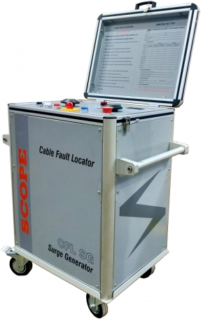
Surge Generator is the backbone of underground cable fault locator test systems. Surge Generator is used with a Prelocator and SIM Filter for fault distance measurement and also used with PinPointer Set for pinpointing the exact fault spot.
SCOPE offers CFL SG 1610, Surge Generator with output of 16kV and 1000 Joules. It is ideal choice for fault location on all types of power cables from LV to HV. CFL SG Series is equipped with different Protections, Interlocks and Auto-discharge Facility to ensure User Safety during operation. User Friendly controls, adequate form factor, contact free HV terminations makes this CFL SG Series most durable and best-designed sets in the segment
Features
- Compact, Lightweight, and housed in rugged aluminum case
- Ideal choice for fault location on all type of power cables
- Backbone of Cable Fault Locator System
- Generates short duration high voltage surge for fault break down
- Built-in Current Coupler to determine the fault distance in conjunction with Prelocator unit
- Repetitive surges applied for pinpointing the exact fault location in conjunction Pinpointing set
- Supports SIM/ARM/MIM method for locating High resistance and flashing faults along with Prelocator and SIM Filter from CFL Series
- Available with optional modes such as DC Hi-Pot, Burn Down and Sheath Fault Location Mode
- Multiple options in a single instrument to avoid carrying several heavy instruments to the site
- Easy setup and intelligent protections make high voltage testing safe & reliable
- Compatible with other models of SCOPE make CFL Series
Specifications
| Parameter | CFL SG 1610 |
| Output Voltage Ranges | 0 – 4kV / 8kV / 16kV selectable |
| Output Energy | Max. 1000J in each voltage range |
|
Impulse Sequence (Surge Rate) |
Single Impulse (Manual) - 3 Sec / 6 Sec / 9 Sec or Single Impulse (Manual) - 2 Sec / 4 Sec / 8 Sec (Optional) |
| Output Indication |
Moving Coil Analog Meter for Output Voltage measurement Moving Coil Analog Meter for Leakage Current measurement in Optional DC Modes |
| Measurement Accuracy | ±5% of selected range |
| Input Supply |
230V AC ± 10%, 50Hz ± 10%, Single Phase, 1.2 kVA max. |
| Cooling Type | Air Cooled |
| Dimensions |
680 x 480 x 660mm without Optional DC Modes 835 x 810 x 880 mm with Optional DC Modes |
| Weight (without trolley and test leads) |
Without Optional DC Modes: 150kg approx. With Optional DC Modes: 155kg approx. |
| Environmental (Operation) |
0°C to 50°C, up to 95% RH (Non-Condensing) |
| Environmental (Storage) |
-10°C to 55°C, up to 95% RH (Non-Condensing) |
| Optional DC Modes | Voltage | Current | Timer / Pulse Ratio* |
| Hi-Pot | 0-16kV | 3/6/12mA | 5/10/15min |
| Burn Down | 0-4/8/16kV | 90/60/30mA | 3min |
| Sheath Fault | 0-8kV | 60mA | *3/6/9s On & 100ms Off |
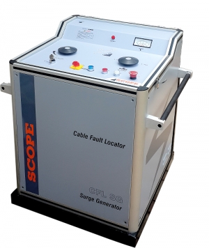
Surge Generator is the backbone of underground cable fault locator test systems. Surge Generator is used with a Prelocator and SIM Filter for fault distance measurement and also used with PinPointer Set for pinpointing the exact fault spot.
SCOPE offers CFL SG 3210, Surge Generator with output of 32kV and 1000 Joules. It is ideal choice for fault location on all types of power cables from LV to EHV. CFL SG Series is equipped with different Protections, Interlocks and Auto-discharge Facility to ensure User Safety during operation. User Friendly controls, adequate form factor, contact free HV terminations makes this CFL SG Series most durable and best-designed sets in the segment.
Features
- Compact, Lightweight, and housed in rugged aluminum case
- Ideal choice for fault location on all type of power cables
- Backbone of Cable Fault Locator System
- Generates short duration high voltage surge for fault break down
- Built-in Current Coupler to determine the fault distance in conjunction with Prelocator unit
- Repetitive surges applied for pinpointing the exact fault location in conjunction Pinpointing set
- Supports SIM/ARM/MIM method for locating High resistance and flashing faults along with Prelocator and SIM Filter from CFL Series
- Available with optional modes such as DC Hi-Pot, Burn Down and Sheath Fault Location Mode
- Multiple options in a single instrument to avoid carrying several heavy instruments to the site
- Easy setup and intelligent protections make high voltage testing safe & reliable
- Compatible with other models of SCOPE make CFL Series
Specifications
| Parameter | CFL SG 3210 |
| Output Voltage Ranges | 0 – 8kV / 16kV / 32kV selectable |
| Output Energy | Max. 1000J in each voltage range |
|
Impulse Sequence (Surge Rate) |
Single Impulse (Manual) / 3 Sec / 6 Sec / 9 Sec or Single Impulse (Manual) / 2 Sec / 4 Sec / 8 Sec (Optional) |
| Output Indication |
Moving Coil Analog Meter for Output Voltage measurement Moving Coil Analog Meter for Leakage Current measurement in Optional DC Modes |
| Measurement Accuracy | ±5% of selected range |
| Input Supply |
230V AC ± 10%, 50Hz ± 10%, Single Phase, 1.8 kVA max. |
| Cooling Type | Air Cooled |
| Dimensions | 835 x 810 x 880 mm |
| Weight (without trolley and test leads) |
Without Optional DC Modes: 150kg approx. With Optional DC Modes: 155kg approx. |
| Environmental (Operation) |
0°C to 50°C, up to 95% RH (Non-Condensing) |
| Environmental (Storage) |
-10°C to 55°C, up to 95% RH (Non-Condensing) |
| Optional DC Modes | Voltage | Current | Timer / Pulse Ratio* |
| Hi-Pot | 0-32kV | 6/12/24mA | 5/10/15min |
| Burn Down | 0-8/16/32kV | 240/120/60mA | 3min |
| Sheath Fault | 0-8kV | 240mA | *3/6/9s On & 100ms Off |
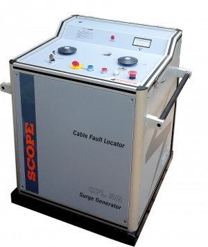
Surge Generator is the backbone of underground cable fault locator test systems. Surge Generator is used with a Prelocator and SIM Filter for fault distance measurement and also used with PinPointer Set for pinpointing the exact fault spot.
SCOPE offers CFL SG 3220, Surge Generator with output of 32kV and 2000 Joules. It is ideal choice for fault location on all types of power cables from LV to EHV. CFL SG Series is equipped with different Protections, Interlocks and Auto-discharge Facility to ensure User Safety during operation. User Friendly controls, adequate form factor, contact free HV terminations makes this CFL SG Series most durable and best-designed sets in the segment.
Features
- Compact, Lightweight, and housed in rugged aluminum case
- Ideal choice for fault location on all type of power cables
- Backbone of Cable Fault Locator System
- Generates short duration high voltage surge for fault break down
- Built-in Current Coupler to determine the fault distance in conjunction with Prelocator unit
- Repetitive surges applied for pinpointing the exact fault location in conjunction Pinpointing set
- Supports SIM/ARM/MIM method for locating High resistance and flashing faults along with Prelocator and SIM Filter from CFL Series
- Available with optional modes such as DC Hi-Pot, Burn Down and Sheath Fault Location Mode
- Multiple options in a single instrument to avoid carrying several heavy instruments to the site
- Easy setup and intelligent protections make high voltage testing safe & reliable
- Compatible with other models of SCOPE make CFL Series
Specifications
| Parameter | CFL SG 3220 |
| Output Voltage Ranges | 0 – 8kV / 16kV / 32kV selectable |
| Output Energy | Max. 2000J in each voltage range |
|
Impulse Sequence (Surge Rate) |
Single Impulse (Manual) / 3 Sec / 6 Sec / 9 Sec or Single Impulse (Manual) / 2 Sec / 4 Sec / 8 Sec (Optional) |
| Output Indication |
Moving Coil Analog Meter for Output Voltage measurement Moving Coil Analog Meter for Leakage Current measurement in Optional DC Modes |
| Measurement Accuracy | ±5% of selected range |
| Input Supply | 230V AC ± 10%, 50Hz ± 10%, Single Phase, 1.8 kVA max. |
| Cooling Type | Air Cooled |
| Dimensions | 835 x 810 x 880 mm |
| Weight (without trolley and test leads) |
Without Optional DC Modes: 160kg approx. With Optional DC Modes: 165kg approx. |
| Environmental (Operation) |
0°C to 50°C, up to 95% RH (Non-Condensing) |
| Environmental (Storage) |
-10°C to 55°C, up to 95% RH (Non-Condensing) |
| Optional DC Modes | Voltage | Current | Timer / Pulse Ratio* |
| Hi-Pot | 0-32kV | 6/12/24mA | 5/10/15min |
| Burn Down | 0-8/16/32kV | 240/120/60mA | 3min |
| Sheath Fault | 0-8kV | 240mA | *3/6/9s On & 100ms Off |
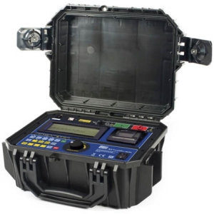
The digital insulation tester model MD5KVR is TENTECH's cutting edge insulation analyzer equipment and it is one of the most complete and sophisticated available in the international market. A software allows for further analysis of tests results, including features such as graphical representation and automatic report generation. Its proven technology provides safe, reliable and accurate measurements of insulation resistances up to 5 TΩ, with 4 preselected test voltages, 500 V -1 kV - 2,5 kV - 5 kV. Other test voltages, from 50 V to 5 kV, can be selected in 25 V or 500 V steps.
A state-of-the-art microprocessor controls the equipment operation and enables the incorporation of advanced features which make measurements easier: auto-range selection, AC/DC voltmeter, automatic measurement of absorption index, polarization index, leakage current and capacitance, timer enabling programming of test duration, configurable pass-fail test, dielectric discharge, ramp test, step voltage test, built-in printer, real time clock and calendar.
Measured values are transmitted through the USB interface and are printed in the built-in printer as a registration of the performed test. Furthermore, the measured values are stored in a non-volatile internal memory. Up to 16,000 measured values may be stored to be transferred afterward to a computer running the T-Logger program. This software allows a further analysis of the test results, including a graphical representation and automatic report generation. The real time clock and calendar, and the sequential test number, facilitates the identification of each test, and the organization of a predictive maintenance system by trend analysis.
The MD5KVR is powered by a rechargeable LFP battery. The cabinet is strong and lightweight, easy to carry, impact-resistant and suitable to be used under severe weather conditions. Thus the megohmmeter supplies very reliable and accurate measurements both in laboratory and out in the field.
Features
- Microprocessor-controlled
- Insulation resistances up to 5 TΩ
- Auto-range
- Automated tests: Absorption index, Polarization index, Capacitance, Leakage current and AC/DC voltmeter
- IP65 protection
- Switchable filter to remove external noise interference
- Real time clock and calendar
- Built-in printer, internal memory for up to 16,000 measured values
- Software for data management
Specifications
| Specification | MD 5KVR | ||
| Test voltage |
500 V - 1 kV - 2,5 kV - 5k V directly, one button selectable. 50 V to 5 kV in 25 V or 500 V steps. DC, negative. |
||
| Maximum resistance reading |
5 TΩ @ 5 kV 250GΩ @250V |
||
| DC Voltmeter |
15 V up to 1,000 Vdc. Accuracy: ±(5% of reading + 3 digits). |
||
| AC voltmeter |
15 V up to 1000 V r.m.s. Accuracy: ±(5% of reading + 3 digits) |
||
| Overvoltage Category | CAT -III 600V | ||
| Capacitance measurement |
50 nF up to 10 µF @ 500 V. 50 nF up to 5 µF @ 1,000 V. 30 nF up to 2 µF @ 2,500 V. 30 nF up to 1 µF @ 5,000 V. Accuracy: ±10% of reading ± 3 digits. |
||
| Short circuit current | Max. 3 mA | ||
| Test voltage accuracy | ± 3% of nominal test voltages on 10 GΩ | ||
| Insulation tester basic accuracy |
± 5% of reading from 1 MΩ to 1 TΩ @ 5 kV. ± 20% of reading from 1 TΩ to 5 TΩ @ 5 kV. (for lower test voltages, the upper limit will be reduced proportionally). ± 20% of reading ± 5 digits 10 from kΩ to 100 kΩ. ± 10% of reading ± 5 digits 100 from kΩ to 1 MΩ |
||
| Advanced features |
Ramp test. Dielectric discharge. Step voltage test. Automated polarization index calculation. Automated dielectric absorption ratio calculation. Programmable pass-fail test. 16,000 readings memory. Switchable filter to remove external noise interference. |
||
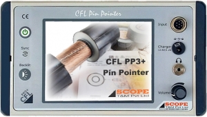
The new generation CFL PP3+ Cable Fault Pin Pointer cum route tracer from SCOPE is the ultimate solution for locating of underground cable faults in minimum time by tracing cable route. It uses an advanced technology which helps even an unskilled operator to locate the fault accurately.
For pinpointing it is used along-with CFL SG Series Surge Generators and for route tracing it is used along-with CFL AG Series Audio Frequency Generators. Advanced technology with features like time-lapse measurement, makes it a tool that can tackle complicated faults easily.
Features
- Compact, Lightweight and Rugged
- Operation via User Friendly 5.7” colour Touchscreen Display
- Universal Receiver used for Route Tracing and Pinpointing
- Backlit facility with intensity control for ease of viewing in direct sunlight
- Simultaneous display of Magnetic and Acoustic waveforms
- Time-lapse / delay measurement facility
- Automatic Fault Point Indication using Coincidence Method
- Noise suppression filters to eliminate external influences
- Mute function for headphones to disable noise while moving
- Specially designed lightweight, neck carrying case ensuring minimum strain to the operator
- Inbuilt Rechargeable Battery
- Water-resistant and dustproof design
- Supplied in an IP67 Class Molded Case
Specifications
| Parameters | CFL PP3+ |
| Channels | Acoustic and Magnetic (Dual Channel) |
| Operating Principle | Coincidence Method |
| Gain | Up to 120dB adjustable for Acoustic & Magnetic |
| Volume limitation warning | 84dB |
| Headphone Jack | 3.5mm |
| O/P impedance of headphone | 8Ω to 72Ω (32Ω is recommended) |
| Acoustic Channel Bandwidth | 70Hz to 3000Hz with automatic filtering |
| Magnetic Channel Bandwidth | 120Hz to 20kHz Auto-tuned |
| Battery | 11.1V Lithium-Ion Rechargeable |
| Charger Input | 90V to 270V AC, 50/60 Hz, Single Phase |
| Operating Time | 10 Hours Min (Approx) |
| Display | 5.7'', 320 x 240 pixel, Colour, TFT Touch Screen |
| Environmental | -20°C to 55°C, 95% RH (Non-Condensing) |
| Dimensions of Receiver | 231mm x 90mm x 135mm |
| Weight of Receiver | 1.6 kg |