
Super User
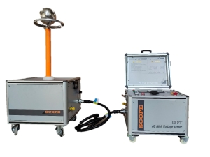
SCOPE offers HPT Series of High Voltage Test Sets capable of injecting variable High Voltage from zero to maximum rated output voltage continuously. Wide range Hi-Pots, up to 50kV, are available in different output options such as power frequency AC or DC or AC-DC Combined. HPT Series is specifi cally designed for safe and accurate measurement of leakage current to evaluate insulation integrity of transformers, motors, insulators, cables etc. Years of Design, engineering and manufacturing experience have made HPT Series of High Voltage Testers the most durable, easily operated and best-designed sets in the segment.
The product was designed considering the importance of safety of the operator and thus we provide independent Control Unit & High Voltage Transformer. The kit has various interlock to avoid any kind of accident while doing the high voltage test set.
Features
- User friendly and simple operation
- Compact, Lightweight and Housed in rugged transport case
- Ideal choice for testing dielectric withstanding capacity of insulation
- Available with the option of Combine or Separate Control Unit
- Analog or Digital meters is provided for displaying output voltage in kV and current in mA
- Different Protections / Interlocks to ensure user safety such as Variac Zero Interlock, Emergency Stop,Overcurrent Protection, Short Circuit Protection, Earth OK Interlock, Input Supply Protection etc.
- User-friendly indications such as Power ON, HV ON-OFF, Earth OK, Over / Under Voltage etc.
- Optional Timer, Foot / Hand Switch and Beacon / Buzzer for additional Safety
- Protective terminals to prevent any accidental contact with HV
- Automatic discharge upon shutdown
Specifications
| Model | Output Voltage |
Max Output Current Option (Imax) |
|||||
| AC | DC | 10mA | 20mA | 25mA | 50mA | 100mA | |
| HPT 3A | 3kV | - | ✔ | ✔ | ✔ | ✔ | ✔ |
| HPT 3D | - | 3kV | ✔ | ✔ | ✔ | ✔ | ✔ |
| HPT 3C | 2kV | 3kV | ✔ | ✔ | ✔ | ✔ | ✔ |
| HPT 5A | 5kV | - | ✔ | ✔ | ✔ | ✔ | ✔ |
| HPT 5D | - | 5kV | ✔ | ✔ | ✔ | ✔ | ✔ |
| HPT 5C | 3kV | 5kV | ✔ | ✔ | ✔ | ✔ | ✔ |
| HPT 10A | 10kV | - | ✔ | ✔ | ✔ | ✔ | ✔ |
| HPT 10D | - | 10kV | ✔ | ✔ | ✔ | ✔ | ✔ |
| HPT 10C | 7kV | 10kV | ✔ | ✔ | ✔ | ✔ | ✔ |
| HPT 15A | 15kV | - | ✔ | ✔ | ✔ | ✔ | - |
| HPT 15D | - | 15kV | ✔ | ✔ | ✔ | ✔ | - |
| HPT 15C | 10kV | 15kV | ✔ | ✔ | ✔ | ✔ | - |
| HPT 20A | 20kV | - | ✔ | ✔ | ✔ | ✔ | - |
| HPT 20D | - | 20kV | ✔ | ✔ | ✔ | ✔ | - |
| HPT 20C | 14kV | 20kV | ✔ | ✔ | ✔ | ✔ | - |
| HPT 25A | 25kV | - | ✔ | ✔ | ✔ | ✔ | - |
| HPT 25D | - | 25kV | ✔ | ✔ | ✔ | ✔ | - |
| HPT 25C | 17kV | 25kV | ✔ | ✔ | ✔ | ✔ | - |
| HPT 30A | 30kV | - | ✔ | ✔ | ✔ | - | - |
| HPT 30D | - | 30kV | ✔ | ✔ | ✔ | - | - |
| HPT 30C | 21kV | 30kV | ✔ | ✔ | ✔ | - | - |
| HPT 40A | 40kV | - | ✔ | ✔ | ✔ | - | - |
| HPT 40D | - | 40kV | ✔ | ✔ | ✔ | - | - |
| HPT 40C | 28kV | 40kV | ✔ | ✔ | ✔ | - | - |
| HPT 50A | 50kV | - | ✔ | ✔ | ✔ | - | - |
| HPT 50D | - | 50kV | ✔ | ✔ | ✔ | - | - |
| HPT 50C | 35kV | 50kV | ✔ | ✔ | ✔ | - | - |
Cable Fault Locator
Underground cable faults cannot be avoided due to many factors such as road widening, infrastructure improvement, digging carried out for repairs of other underground utilities etc.
These faults generally take long time to detect and hence long time to repair the damaged cables and restore the power supply. Long outages cause heavy production loss to industries, revenue loss to power distribution companies and inconvenience to general public. This calls for quick fault location and restoration of power supply in minimum possible time.
An ordinary fault locating kit comprising of diagnosis set and pin-pointing equipment can take long time to locate fault point. SCOPE offers pre-locator instruments that can give the fault distance to help the operator for reaching the spot quickly and pin-pointing the fault in a short time.
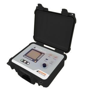
CFL PL3, new generation Cable Fault Pre-Locator from SCOPE is the ultimate solution for locating underground cable faults in minimum time. It uses advanced technology for fault distance measurement which helps even an unskilled operator to locate the fault with accuracy.
CFL PL3 is an advanced fault locating instrument. Three operating modes offered by the instrument enable the operator to locate all types of faults on any cable in minimum possible time.Complex and difficult to locate nature fault are located by CFL PL3 with high accuracy. These features classify the instrument to be a part of fault locating kit of Heavy Industries & Power Distribution Company.
Features
- Measuring rage up to 16 km.
- Large LCD & User friendly operation.
- Adjustable Balance of instrument resistance to suit the cable under test.
- Adjustable Gain for optimal waveform resolution.
- Facility to store & compare the waveforms.
- Memory to store up to 50 waveforms.
- Housed in rugged, IP class moulded case.
- PC connection via RS 232.
- Printer connection via RS 232 (Printer is optional).
- Compact and light weight.
- Large range of Propagation Velocity from 90 to 300m/μS covers all type of cables including-pilot and telecom able with any type of insulation.
Specifications
- Transmitting Pulse Amplitude : 30V
- Transmitting Pulse width : 40ns-3.56μs
- Voltage withstand : 400V AC (50Hz)
- Output impedance : 5-80Ω
- Measuring Range : 0-16 km
- Sampling Speed : 100MHz
- Resolution : TDR Mode and SIM Mode : <± 1m up to range <4km <± 4m for ranges >4 km ICM Mode : <± 4m up to range <4 km <± 16m for ranges >4km
- Propagation Velocity : 90-300m/μs.This range covers all the cables including pilot and telecom cable with any type of insulation.
- Ranges : 500m, 1km, 4km, 5km, 8km & 16km. The operator can choose right range to get better resolution at fault point.
- Balance Adjustment : Under TDR mode it is required to balance the instrument resistance to suit the cable under test with this control the instrument resistance can be varied between 5 ohms to 79 ohms.
- Memory : 50 waveforms
- Display : 320x240 pixels
- Charging voltage : Input: 230V AC: Output: 8.4V±10% DC
- Operating time of rechargeable batteries: Approx. 5hrs
- Operating Temperature : -10˚C to 50˚C
- Storage Temperatures : -10˚C to 70˚C
- Type of protection IP 54 : Splash proof and dust protected
- Dimensions : 330 x 305 x 152mm
- Weight : 3kg

XC 2100E, a Fault Location System based on principle of travelling wave detection is the solution to above problem. It can detect not only permanent fault, but also transient fault within one tower span accuracy (with best accuracy of ±50 meters). It is a kind of Line Monitor for continuous monitoring of transmission lines and gets triggered whenever travelling waves are generated on line due to switching, lightening or fault.
There are various methods employed for fault location detection. However the most suitable is Double End Method in which XC 100E are installed on both ends of the line, and are time synchronised by built-in GPS Module.
The data from both Units is brought to a Master Station where the Master Station Software XCF 2100E is installed. It automatically calculates the distance of fault from each end of line. Each XC 100E is capable of monitoring up-to 8 lines and the Master Station Software is capable of handling large no. of lines in a network.
Features
- TWFL system is free from influence of following factors which aff ect fault location accuracy of impedance based measurement methods like:
- Resistance of line
- Voltage & Current Transformer (CT & PT) errors
- Insufficient accuracy of line parameters due to neglecting of line transposition, distributed capacitance etc.
- Uncertainty of zero sequence impedance due to variation of earth resistance along the line corridor
- Load flow
- TWFL system monitors travelling waves at both ends of transmission lines & provides accurate fault location(fault distance, tower number) for all type of power lines including:
- AC, HVDC and Series Compensated Transmission Lines
- Lines with T branches
- Lines containing cable and overhead line sections
- Measuring fault distance of single phase to ground fault in non-eff ectively earthed Distribution System
- Travelling wave measurement technique used gives fault location within one tower span and with best accuracy of ±50 meters irrespective of line length, line parameters, fault resistance, CVT transients, conductor & tower geometry.
- Such accurate fault location greatly reduces the search time to find out the fault to help quick recovery of the system.
Specifications
| Parameter | XC-2100E |
| No. of Channels | 3-24 configurable for 1-8 line |
| Input Module | AD Module: Direct current input from substation Protection CT |
| AI Module with split core CT: Current Input through a split core CT | |
| AI Module with external CT: Current Input through an external CT | |
| AV Module: Input from substation VT | |
| Length of Transient Record | 1 to 20ms Programmable |
| Power | 85 to 264V, 50/60 Hz AC or 90 to 260V DC |
| Sampling Frequency | 36 MHz, 12 MHz, 8 MHz, 6 MHz, 4.8 MHz, 4 MHz, 3 MHz, 2.4 MHz, 1.5 MHz, 1 MHz & 500 kHz |
| Accuracy of Fault Location | Best Accuracy to ±50 meter |
| GPS Accuracy | 100ns |
| Memory | 8 GB |
| Communication port | 2 Ethernet ports, 2 DB9 RS232, USB |
| Communication protocol | IEC60870-5-104, IEC 61850 |
| Immunity | Conforms to relevant IEC standards |
| Operating Temperature | - 10°C - 55°C |
| Storage Temperature | -40°C to 85°C |
| Physical Dimension | 2U, 19” |

This is an ‘All in One’ solution for testing and analysing partial discharges in the insulation of high-voltage transformers, cables, GIS and electric machines. The DIMRUS ‘PD Analyser’ help diagnose their insulation state and find any type of defects very effectively.It can be used for temporary or constant monitoring of partial discharge in medium and high voltage systems and cables of any rated voltage.The PD Analyser is the most useful device for condition estimation of high-voltage insulation. This multipurpose device is designed for -
- Partial discharge measuring in high-voltage insulation at a high noise level.
- Fast detecting of the defects in different high-voltage equipment and identifying how dangerous they are.
Features
- It separates stray noise pulses and partial discharge pulses while comparing their frequency and time of arrival.
- It uses phase resolved partial discharge (PRPD) and time frequency analysis (PD- Cloud).
- It has the database of the most defects which can be upgraded with new diagnostic information.
- Danger level shows how severe the signal can be.
- It uses special algorithms to estimate if the received data is authentic.
- Automatic report generation on the condition of the insulation of the high-voltage equipment.
Specifications
| Parameters | PD Analyser 3 | PD-Analyzer HF/UHF |
| Sensor options | HF, UHF | HF, TEV, UHF |
| HF discharge pulse frequency | 0.1 to 20 MHz | |
| UHF discharge pulse frequency | 200- 1500MHz | |
| HF discharge amplitude | 20 to 100000pC | |
| UHF discharge amplitude | -70dBm to -25dBm | |
| Computer connection | USB, Wi-Fi | USB |
| Supply voltage | 90 to 260V AC | |
| Operating temperature range | -10 to 50 | |
| Dimension | 222 x 160 x 45 mm | 520 x 435 x 230 mm |
| Weight | 12 Kg | 25Kg |
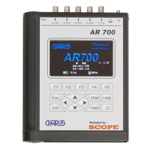
PD Defect Location in High-Voltage Equipment Insulation by Acoustic Sensors To act on deteriorating insulation the source of PD must be known.The insulation defects produce partial discharges, which emits electrical impulses, radiation of electromagnetic waves as well as acoustic signals.The AR700 measures acoustic signals with multiple sensors spread over the transformer. Then the software determines the failure location using the time difference of all incoming signals. Finally, these coordinates are shown in a 3D model of the transformer. AR700 device is used for measuring of acoustic signals on the external surfaces of gas-insulated breakers and substations, power transformers and other tank high-voltage equipment. The acoustic signals are caused by partial discharges in the insulation, which is the sigh of the defects.The advantage of “AR700” device is the quick installation of the acoustic PD sensors on the external surface of high-voltage equipment tank. The sensors have magnetic holder that is why there is no need to de-energize the equipment for the sensors installation. “AR700” device has 4 syn-chronic channels for acoustic signal measurement. This gives the possibility not only to find the defects in the insulation, but also to locate them. The location function of the “AR700”device is unique for acoustic devices.
Features
- The signal analyses and the PD zone location could be carried out both in manual and automatic modes.
- Software calculates the fault location based on the time difference between the incoming signals.And report is generated about PD source location.
- Convenient and handy through light weight, small size and battery operation.
- Can be used for multiple assets like Transformers, CTs, GIS, Cables etc.
- Defect type identification by synchronised measurement of PD
| Parameter | AR700 |
| Acoustic channels for PD measuring | 4 |
| Frequency range of acoustic sensors | 30 - 300 kHz |
| High-frequency channels for PD measuring | 1 |
| Frequency range of high-frequency sensors | 0.1 - 20 MHz |
| LCD resolution | 480x272pixel |
| PC connection | USB |
| Operating temperature range | -20 to +60 ºc |
| Humidity | <98%, noncondensing |
| Operating time from build-in accumulator | 8 hours |
| Device weight, without sensors | 1.1 kg |
| Dimensions of transportation case | 520x435x230mm |
| Device weight in carrying case | 12kg |

SWITCHGEAR AND CABLE MONITORING SYSTEMS.
The portable multipurpose 3i device (Intellectual Insulation Indicator) is for eff ective high-voltage equipment insulation monitoring on-line. The 3i device measures and analyses partial discharges (PD). For eff ective PD measurement and noise rejection, there are two types of sensors used in the device: the acoustic sensor and the TEV sensor. Both the sensors are built into the device case, and so do not need any connection cables. The device is supplied in a strong metal case; at the faceplate there are the colored screen and two buttons: power button and function button.
Features
- 6 - 35 kV switchgears of various designs;
- Terminations and joints of cables;
- High-voltage gas-insulated equipment (Gas-Insulated switchgear (GIS)) of any rated voltage.
- The tanks of power transformers, breakers, etc.
- The multipurpose 3i device is for on-line insulation condition estimation in the following equipment:
Specifications
| Parameter | 3i |
| In-built PD sensors | acoustic, TEV |
| In-built acoustic sensor frequency range, kHz | 40 ± 2 |
| In-built TEV sensor frequency range, MHz | 10 - 100 |
| LCD resolution, pixels | 240 x 320 |
| PC connection | USB |
| Battery life, hours | 10 |
| Operation temperature range, °C | -20 ÷ 40 |
| Device dimensions, mm | 187 x 78 x 43 |
| Weight, kg | 0.6 |
SCOPE introduces 50 A state of the art precision winding resistance meter, specially designed for field testing as well as factory testing of large transformers up to 500 MVA. Winding resistance value of transformer and rotating machine are directly displayed on 5.7” TFT display. TRM 50 is designed to work in live EHV switchyard conditions, ensuring operator’s safety and repeatability of results. Maintenance time saving is ensured by one time connection to transformer with simultaneous resistance measurement of three / six windings, measurement of resistances of all taps with automated tap change and demagnetization facility. The meter is protected against the back-EMF offered by large inductive windings.
Features
- Can measure DC winding resistance of large rotating machines, highly inductive test objects like Transformer, Generators and Motors etc.
- 50 A DC current makes it possible to measure low resistances with high accuracy.
- One time connection to either all windings of primary and / or secondary. Simultaneous measurement reduces connection and measurement time.
- Change in winding resistance, short or open windings can be detected from measured values.
- Automatic temperature measurement and temperature corrected value calculation.
- Measurements of winding resistance of all taps of phases in one go. Recoding, printing and storage of results.
- OLTC contact opening and compete OLTC performance test facility. Testing of either single or three phases in one test. Single report generation.
- To know condition of OLTC contacts, OLTC mechanism, transition resistor.
- Discharges and demagnetizes the object after test.
Specifications
| Parameter | TRM 50/ TRM 50+ |
| No of Channels | 3/6 Current Channels, 3/6 Volatge Channels , 1 tempreture Channel |
| Connections | One time connection to primary or secondary winding of transformer |
| Current Ranges | 50A, 40A, 25A, 10A, 5A, 1A, 100mA, 10mA |
| Resistance Ranges | Up to 2000 Ω (Auto ranging) |
| Resolution | 4 ½ digit |
| Accuracy | Value ± 0.5% ± 5 counts |
| Current and Resistance ranges | |
| Open Circuit Voltage | 50 V |
| Demagnetization Facility | Yes |
| Display | 5.7” TFT display with touch screen |
| Printer | 58 mm, Inbuilt thermal printer |
| Communication Port | Ethernet for PC communication |
| Data Port | USB for extrernal memory stick connection |
| External Control | Possible via Notebook PC through Ethernet port and software |
| Temperature measurement | Range 0 to 100 deg, Accuracy ± 1 deg, Resolution 0.1deg |
| Temperature correction | For Aluminium & Copper |
| Temperature Input Channel | Compatible to accept RTD input |
| User Interface | Resistive touch screen |
| Back EMF Protection | Yes. Automatic protection after measurement and during accidental disconnection of current path. Protection operates even if Mains supply fails. |
| Discharge Facility & Indication | Automatic Discharge of DUT & messages on screen |
| Tap Changer Test | Detects discontinuity during tap changer test |
| OLTC Test Facility(Optional) | OLTC test facility with current v/s time graph, Single or Three Phases simultaneously. Available in control through PC option only. |
| OLTC current Ranges | 50A, 40A, 25A, 10A, 5A |
| Protection | Shut down of power source on Over voltage, Over current,Over temperature |
| Indications | Polarity reversal, Test connection continuity and discharge |
| Diagnostics Check | At power On instrument does self-check of channels and shows the message |
| Test Leads | Measuring leads, AC supply, earth leads and temperature sensor lead |
| Operating Environment | -10°C to 50°C, 95% RH (non condensing) |
| Storage Temperature | -20°C to 60 °C |
| Heat Run test | Yes |
| Delta connection Measurement | values of each arm of delta winding is calculated and displayed |
| One side earthing | Instrument is able to do the measurement with one side earthing (with Neutral earthing) |
| Input Supply | 110V AC ±15% 50/60 Hz ±10% Or 220V AC ±15% 50/60 Hz ±10%. |
| Dimensions | 630 x 500 x 302mm |
| Weight | 22 Kg. Approx |

SCOPE introduces state of the art precision three phase Transformer Turns Ratio Meter (TTRM ) designed for field testing as well as factory testing of power transformers, instrument transformers and distribution transformers of all types. Along with turns ratio, this light weight and reliable instrument measures ratio deviation, phase angle deviation, magnetizing current and detects tap-position of single as well as three phase transformers in charged switchyard condition. The instrument has facility to automatically detect vector group of all majority configurations available. The differant AC voltage selection offers high accuracy in measurement.
Instrument has in-built TFT display with touch screen and thermal printer. The user friendly, simple instrument makes the testing more easy. With the touch keypad it is possible to enter required DUT information. The ratio results of all the phases are displayed in tabular form with % error. Internal non volatile memory gives the provision of storing test results. Further data can be downloaded to PC or copied to memory stick through USB port provided. The CTrans-TTRM software, gives the flexibility to download the stored results to PC and do the further analysis and report generation.
Features
- Different voltage ranges provided for more accurate results
- 5.7” TFT display with touch screen and simple menus to operate TTRM
- Facility to configure transformer ID and details
- Automatic OLTC operation for tap change
- Date and time stamping to results
- In-build memory to store the test results
- Thermal printer to take quick print out for record
- Ethernet port for PC interface to transfer records to PC Software
- Mass storage device (USB 2.0) interface for copying records in pen drive
- Lightweight,portable instrument household in rugged moulded case
Specifications
| Parameter | Display | Range | Resolution | Accuracy | |
| 1 | Turns Ratio | 1.9999 : 1 | 0.8-20000 : 1 | 5 Digit |
0.8 - 100: ± 0.05% @ 10V 101 - 1000: ± 0.05% @ 10V 1001 - 1500: ± 0.05% @ 10V 1501 - 2000: ± 0.10% @ 10V 2001 - 4000: ± 0.20% @ 10V
0.8 - 100: ± 0.05% @ 40V 101 - 1000: ± 0.05% @ 40V 1001 - 1500: ± 0.05% @ 40V 1501 - 2000: ± 0.05% @ 40V 2001 - 4000: ± 0.05% @ 40V 4001 - 13000: ± 0.25% @ 40V
0.8 - 100: ± 0.03% @ 100V 101 - 1000: ± 0.05% @ 100V 1001 - 1500: ± 0.05% @ 100V 1501 - 2000: ± 0.05% @ 100V 2001 - 4000: ± 0.05% @ 100V 2001 - 4000: ± 0.05% @ 100V 4001-13000: ± 0.15% @ 100V 13001 - 20000: ± 0.20% @ 100V |
| 2 | Excitation Current | 0.1mA to 1.999A | 0-2A | 0.1mA | ± 1mA |
| 3 | Phase Deviation | 0.05 Deg to +179.95 Deg | ± 180 Deg | 0.05 Deg | ± 0.05 Deg |
| Parameters | TTRM 302 |
| No of channels | Three HV channels and three LV channels |
| Test Voltages | 10V, 40V and 100V AC selectable voltages |
| Measurements |
Ratio, Ratio error, Phase Angle Deviation, Excitation current, Vector group and Magnetic balance (optional) |
| OLTC Control | Raise and Lower control to operate OLTC |
| Test Results Display | 5.7” touch-screen (TFT) display, thermal printer |
| Test Leads | Suitable to test EHV Transformers |
| Paper | Thermal, 58 mm wide roll form |
| Memory | Up to 50000 records inbuilt memory, with date and time stamping |
| Power | (110V ± 15%) / (60Hz ± 10%) OR (230V ± 15%) / (50Hz ± 10%), 75VA. |
| Communication Port | Ethernet port for PC Communication, USB port for data downloading to pen-drive |
| Housing | IP 65 rated moulded case |
| Operating Environment | -20°C to +55°C, 95%RH (non-condensing) |
| Storage Environment | -40°C to +60°C, 95%RH (non-condensing) |
| Dimensions | 435 X 315X 175 mm. (Max.) |
| Weight | 10 Kg Approx |
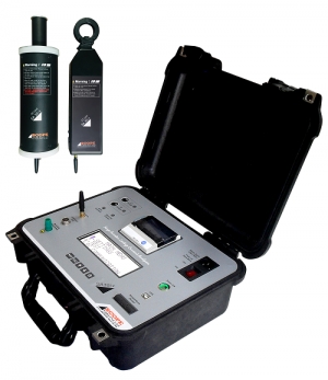
SA 30i+, the wireless Leakage Current Analyser from SCOPE is a State of the Art, On-line test system for Residual Life Assessment of Metal Oxide Surge Arresters. The instrument measures and directly displays the values of Total Leakage Current and Third Harmonic Resistive Leakage Current. It provides system harmonic compensation as per IEC 60099-5-B2. It provides Corrected Resistive Leakage Current after applying correction factors for change in system voltage & temperature.
The SA 30i+ can be pre-loaded with the LA identity details (LA Identification, Type, Serial Number,Location, Rated Voltage etc.) and tests conducted on the same ID of the arresters are saved under the same folder. Trend analysis software, SAData picks up this data and stores them in a similar fashion on a PC. This analysis software enables the user to take a decision to repair/replace the arresters considering safety limits.
SA 30i+ is designed to work under the hostile electrostatic noise found in live EHV switch yards upto 765 kV
Features
- Safe Online measurement due to wireless CT and Field Probe
- In built temperature measurement facility enables calculation of temperature corrected leakage currents.
- Correction of results to rated voltage of LA to eliminate eff ect of change in system voltage.
- Date and time stamp on test results Results are displayed on large font, Big, back-lit LCD, printed on in-built thermal printer and can be stored in memory of the instrument.
- SA 30i+, CT unit and Field Probe unit are powered by easily available re-chargeable Lithium-ion batteries. It works for a day’s testing needs on a single charge
- The SA 30i+ is a switchyard compatible instrument. This makes the instrument extremely convenient to use.
- Built-in standard calibration source and self-calibration check facility
- USB communication port to transfer data to PC and Windows based PC Downloading & Analysis Software.
- Facility for testing of GIS LAs available optionally
Specifications
| Parameter | SA30i+ |
| Total Leakage Current Range | 1 μA to 20 mA |
| Resistive Leakage Current Range | 1 μA to 20 mA |
| Resolution | 1 μA |
| Accuracy | Value ± 5% ± 1 μA |
| Inputs | Wireless Clamp on CT and Wireless Field Probe optional external field PT Input (Voltage Peak method as per IEC 60099-5-A1 for GIS) |
| Display | 4 line x 20 character large backlit LCD with large font |
| Compensation | Automatic for System Harmonics, Temperature & System Voltage |
| Temperature Sensor |
Inbuilt Platinum Resistance Thermometer with measurement range of -20°C to 55°C |
| Self-calibration Check | Available |
| PC Connectivity | USB Port (Standard), RS 232 & Ethernet (Optional) |
| Memory | Storage capacity of 2000 results |
| Printer | 58mm Inbuilt Thermal Printer |
| Power |
Battery as well as Mains powered Main Unit Battery powered CT and FP Units |
|
Internal Battery |
SA30i+ - 11.1 V / 2200mAh Internal Rechargeable battery, CT Unit - 11.1 V / 1150mAh Rechargeable battery, Field Probe Unit - 11.1 V / 1150mAh Rechargeable battery. 8 hours Battery life with full charge |
| Mains Supply | 88 to 264 VAC, 47 to 63 Hz, Single Phase |
| Battery Charger | Inbuilt in Main Unit, Connection to CT and Field Probe Provided |
| Dimension
|
SA30i+ - 340 x 295 x 155 mm, CT Unit - 340 x 73 x 40 mm, Field Probe Unit - 340 x 82 mm Cylindrical |
| Weight
|
SA30i+ - 3.8 Kg, CT Unit - 0.7 Kg , Field Probe Unit - 0.75 Kg |
| Environment |
-20°C to 55°C, up to 95% RH (non-condensing), Storage Temp - 0-70°C |
|
Type Testing |
As per IEC 60068 / IS 9000 for Dry Heat, Damp Heat, Change of Temperature, Bump, Vibration and Mechanical Shock. For EMI / EMC & Safety as per relevant IEC Standards |

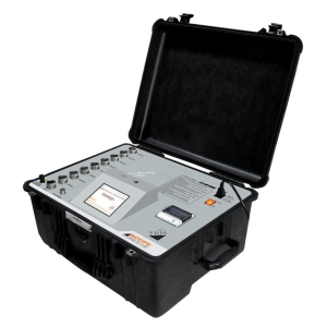
The CFL SIMF, Cable Fault Secondary Impulse Filter from SCOPE is the ultimate solution for locating underground cable faults in minimum time. It uses advanced technology for fault distance measurement which helps even an unskilled operator to locate the fault accurately.
Cable Fault Secondary Impulse Filter CFL SIMF is mainly used for high resistance and flashing fault test for power cable with the voltage below 10kV, and for fault location with Secondary Impulse with the conjunction of Pre-locator and HV surge generator. Latest fault locating technique for high resistance and flashing faults is Secondary Impulse Method (SIM). This method offers highly reliable results for faults on any type of power cable. It converts the faults to low resistance nature by creating an arc across the fault.
It is a passive filter having its own output power source. It uses the energy of the surge generator to create an arc at the fault point. A high voltage switch incorporated in the output circuit facilitates selection of SIM or ICM mode.